
car tracking device circuit diagram
The car tracking device operates on the principle of radio frequency transmission and reception. The tank circuit, formed by C2 and L1, is critical for generating a resonant frequency that matches the frequency of the transmitter, ensuring efficient signal transmission. The coupling capacitor C3 plays a vital role in linking the transmitter to the antenna, which can be tailored to the specific application requirements, whether through a telescopic design for portability or a simple hookup wire for ease of construction.
On the receiver side, the signal tuning is accomplished through the combination of C4 and L2, which filters and amplifies the incoming signal before it reaches the 741 operational amplifier. This amplifier is responsible for further processing the signal, amplifying it to a level suitable for detection and interpretation by the LED indicators. The five LEDs provide a visual representation of the signal strength, enabling users to ascertain the proximity and direction of the tracked object.
During the tuning process post-construction, it is essential to ensure that the transmitter is adjusted correctly so that the maximum number of LEDs illuminate, indicating optimal signal reception. The variable resistor Rv2 allows fine-tuning of the receiver's sensitivity, ensuring that the strongest signal is registered when the receiver's antenna is aligned with the transmitter. This careful calibration is crucial for effective operation of the tracking device, enhancing its reliability and performance in real-world applications.Tank circuit C2 and L1 is used to tune the transmitter. The antenna is coupled to the transmitter through C3 and must be a telescopic antenna or a length of hookup wire. At the receiver, the incoming signal is tuned by C4 and L2 before being passed on to the 741 IC. To find the object using this car tracking device is use a visual indications wit h 5 LEDs which indicate the signal strength. After build, the car tracking device ( receiver and transmitter ) will need to be tuned. We need to tune the transmitter until all of the receiver`s LEDs light and adjust Rv2 until you get a maximum strength reading only when the receiver`s antenna is pointed directly at the transmitter. 🔗 External reference
Related Circuits
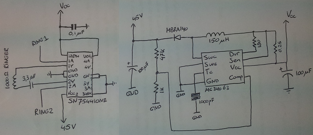
The process involves adapting an old phone for Bluetooth functionality, specifically testing the ringer circuit constructed using schematics from Sparkfun. When connecting a section of the schematic to a 3.5V source (Vcc), an output voltage of 45V is observed,...
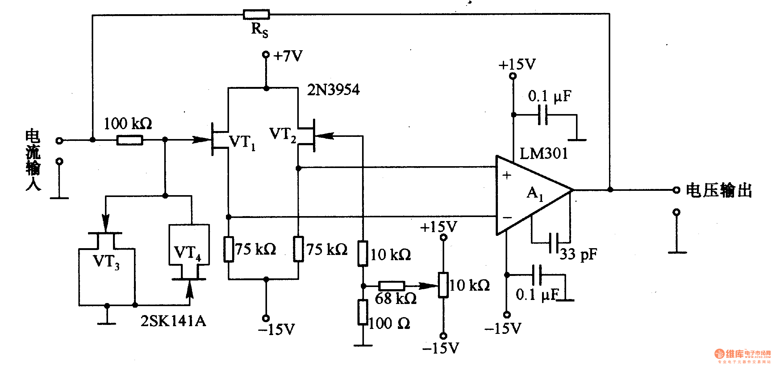
This is a low-input impedance conversion circuit with the reference resistor RS connected to the amplifier's feedback loop, resulting in an input impedance close to zero. The input current flows into the output end of the operational amplifier (Op-Amp)...
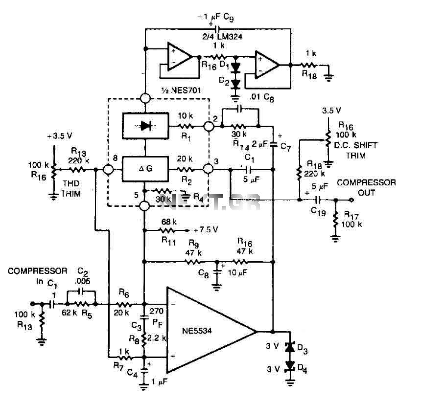
This circuit for a compressor utilizes a high-fidelity external operational amplifier (op amp) with high gain and wide bandwidth. A compensation network at the input is required for stability. The rectifier capacitor (Cg) is not grounded; instead, it is...

The ramp voltage from the low-frequency oscillator IC1 modulates IC2, thereby producing a rising and falling tone similar to the wail of police cars. The described circuit utilizes a low-frequency oscillator (IC1) to generate a ramp voltage. This ramp voltage...
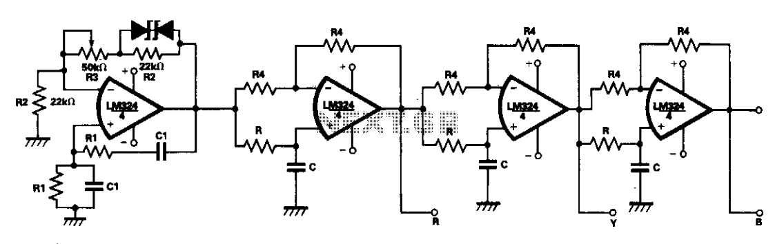
A single LM324 chip can effectively reduce the size of a 3-phase waveform generator through the use of active R-C networks, making it advantageous for compact and stable 3-phase inverters. One quarter of the LM324 functions as a Wien...
This is a battery charger circuit that has the advantage of automatically disconnecting the battery when charging is complete. The voltage sensor used in this circuit is the LM301 IC, which serves to disconnect the battery when the charging...
Warning: include(partials/cookie-banner.php): Failed to open stream: Permission denied in /var/www/html/nextgr/view-circuit.php on line 713
Warning: include(): Failed opening 'partials/cookie-banner.php' for inclusion (include_path='.:/usr/share/php') in /var/www/html/nextgr/view-circuit.php on line 713