
Car wireless alarm
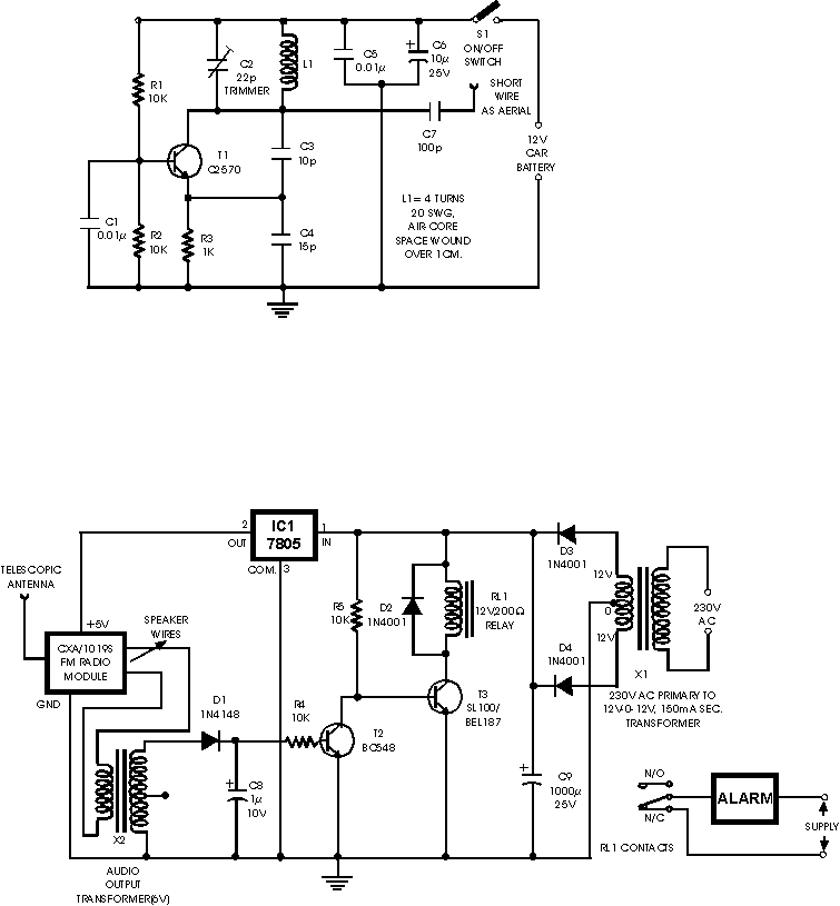
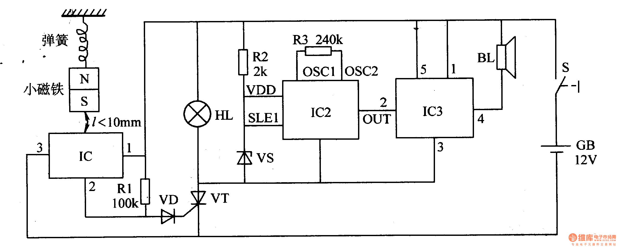
The FM radio-controlled anti-theft alarm system operates on a low-voltage DC supply, making it suitable for a wide range of vehicles. The system consists of two main components: the transmitter and the receiver. The transmitter, a mini VHF FM unit, is discreetly installed in the vehicle and is activated when the vehicle is parked. The receiver, based on the CXA1019 FM radio module, is placed inside the vehicle and is tuned to the frequency of the transmitter.
Under normal conditions, when the transmitter is operational and the receiver is properly tuned, the output remains quiet, indicating a stable link between the two devices. In this state, the transistor T2 (BC548) remains in the off state, preventing any current flow through the relay driver transistor T3. The relay remains energized, maintaining the system in a secure state.
When an unauthorized attempt is made to move the vehicle, the radio frequency link is disrupted. This interruption triggers the FM receiver to generate a hissing noise, which is an indication of a lost signal. The hissing sound is coupled into the relay switching circuit through an audio transformer, which converts the audio frequency signals into a usable form for the relay control.
The AC signals are then rectified by diode D1, producing a pulsed DC signal that is smoothed by capacitor C8. This rectified voltage provides the necessary forward bias to transistor T2, causing it to conduct. As a result, the base of transistor T3 is pulled to ground, effectively turning it off and deactivating the relay. This action triggers the alarm system connected to the normally closed (N/C) contacts of the relay, alerting the owner to the attempted theft.
The design of the system ensures that it remains functional even if the transmitter is disconnected from the battery. In the absence of a signal, the receiver continues to produce the hissing output, maintaining the alarm state. This redundancy enhances the reliability of the system, making it a robust solution for vehicle security. Overall, the FM radio-controlled anti-theft alarm is an effective and efficient method of deterring vehicle theft while providing peace of mind to vehicle owners. This FM radio-controlled anti- theft alarm can be used with any vehicle having 6- to 12-volt DC supply system. The mini VHF, FM transmitter is fitted in the vehicle at night when it is parked in the car porch or car park.
The receiver unit with CXA1019, a single IC-based FM radio module, which is freely available in the market at reasonable rate, is kept inside. Receiver is tuned to the transmitter's frequency. When the transmitter is on and the signals are being received by FM radio receiver, no hissing noise is available at the output of receiver.
Thus transistor T2 (BC548) does not conduct. This results in the relay driver transistor T3 getting its forward base bias via 10k resistor R5 and the relay gets energised. When an intruder tries to drive the car and takes it a few metres away from the car porch, the radio link between the car (transmitter) and alarm (receiver) is broken. As a result FM radio module gene-rates hissing noise. Hissing AC signals are coupled to relay switching circ- uit via audio transformer. These AC signals are rectified and filtered by diode D1 and capacitor C8, and the resulting positive DC voltage provides a forward bias to transistor T2.
Thus transistor T2 conducts, and it pulls the base of relay driver transistor T3 to ground level. The relay thus gets de-activated and the alarm connected via N/C contacts of relay is switched on. If, by chance, the intruder finds out about the wireless alarm and disconnects the transmitter from battery, still remote alarm remains activated because in the absence of signal, the receiver continues to produce hissing noise at its output. So the burglar alarm is fool-proof and highly reliable. 🔗 External reference
Related Circuits
The mute pin of this dual audio amplifier serves as the trigger for a single-chip high-temperature alarm. One half of the integrated circuit (IC) functions as an oscillator, while the other half amplifies the audio alarm outputs to 10W. The...
In this tutorial, the functioning of the memory card circuit in mobile phones will be explored. The previous post discussed the pin-outs and types of memory cards utilized in cellular devices. The accompanying block diagram illustrates how the removable...
The SLA battery is charged from the vehicle's battery. When the engine is running, the voltage remains fairly constant, which greatly simplifies the charging circuit. If the SLA battery is fully charged, any further charging current from the vehicle...
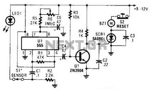
The alarm circuit utilizes a single 555 oscillator/timer (U1) that functions in both the alarm-trigger circuit and the entry-delay circuit. In this configuration, the trigger input of U1 at pin 2 is maintained in a high state through resistor...
During rainy seasons, it can be quite bothersome when the car wipers operate continuously without pause. Have you ever considered implementing speed control for the wipers? While there are wiper control modules available commercially, many of them can be...
When the switch is activated, the seismic alarm enters a detection mode. In the absence of an earthquake, pin 3 of IC1 outputs a low signal, resulting in the disconnection of VT, which keeps the alarm circuit inactive. Upon...
Warning: include(partials/cookie-banner.php): Failed to open stream: Permission denied in /var/www/html/nextgr/view-circuit.php on line 713
Warning: include(): Failed opening 'partials/cookie-banner.php' for inclusion (include_path='.:/usr/share/php') in /var/www/html/nextgr/view-circuit.php on line 713