
Carrier-current-fm-receiver
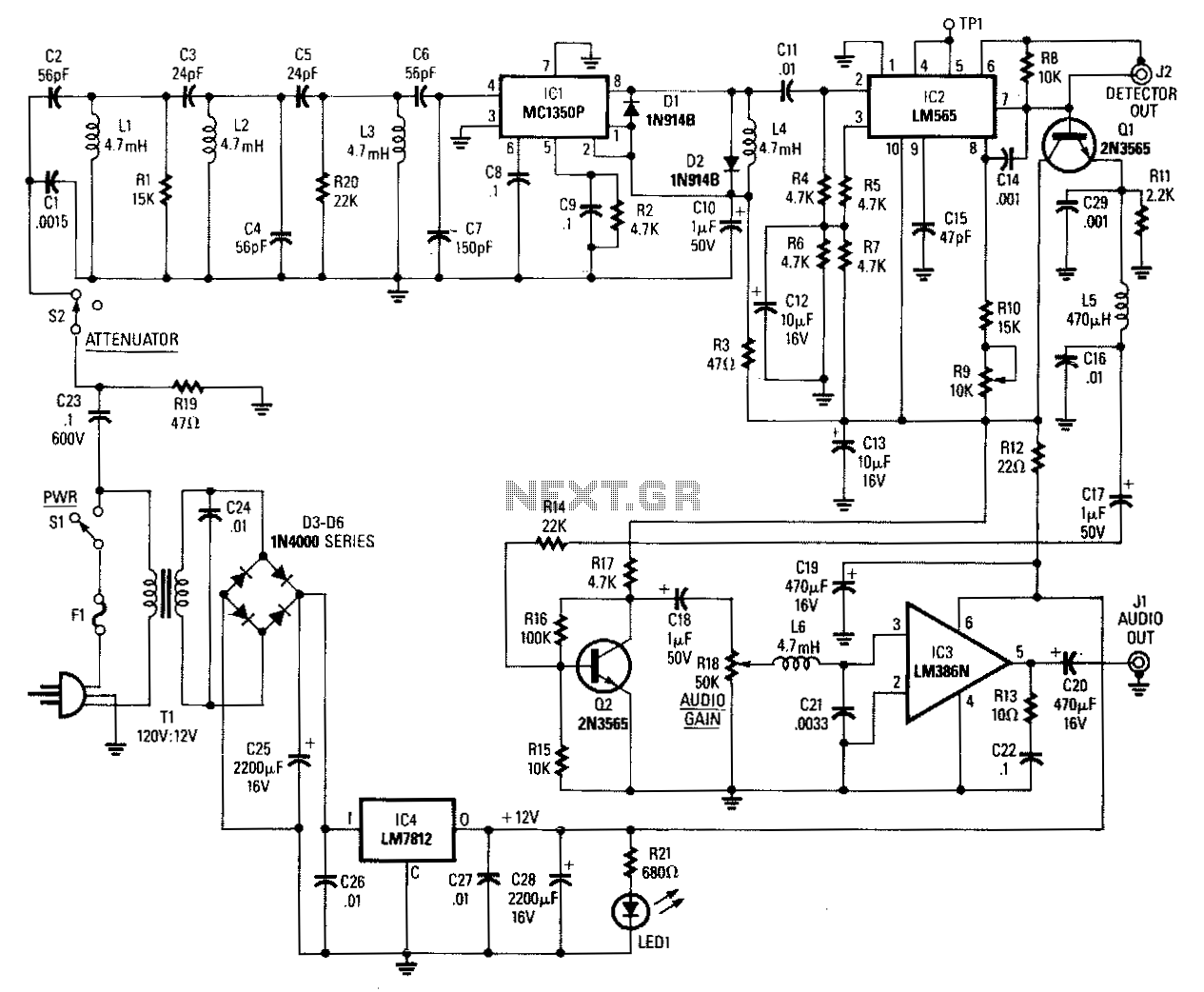
Input signals from the power line are coupled through C23 and R19 to the input filter network. C23 must be rated at 600 volts. Switch 52 is used as an attenuator. Components C2 through C7, L1 through L3, R1, and R20 form a triple-tuned bandpass filter with a passband from 220-340 kHz. Signals from the filter are fed to an MC1350P gain block IC, which serves as a tuned RF amplifier. IC2, the LM565 PLL, functions as an FM demodulator. Pins 8 and 9 are connected to an internal VCO, and components R9, R10, and C15 set the VCO's free-running frequency. The VCO signal and the input signal from pin 2 are compared in the phase detector. The output from the phase detector is internally amplified and appears at pin 7. The output at pin 7 is a replica of the original modulation on the FM input signal to the receiver; thus, the output at pin 7 is the recovered audio. C17 and R14 couple audio to the base of Q2, which, along with R15, R16, R17, and C18, forms an audio amplifier that raises the recovered audio to approximately 1 V peak-to-peak. The signal is then fed into an LM386N audio amplifier, capable of delivering up to 12 W of audio, coupled via C20 to any standard 8-ohm external speaker. The kit is available from North Country Radio, P.O. Box 53, Wykagyl Station, NY 10804.
The circuit described involves a series of interconnected components designed to process and amplify audio signals derived from FM-modulated input. The initial signal coupling occurs through capacitor C23 and resistor R19, which are crucial for filtering and isolating the input power line signals from the subsequent processing stages. C23 is specifically rated for 600 volts, ensuring it can handle the expected voltage levels without failure.
The triple-tuned bandpass filter constructed from capacitors C2 to C7 and inductors L1 to L3, along with resistors R1 and R20, is designed to allow frequencies between 220 kHz and 340 kHz to pass while attenuating signals outside this range. This selectivity is essential for effective RF amplification, which is carried out by the MC1350P gain block integrated circuit (IC).
The FM demodulation process is facilitated by the LM565 phase-locked loop (PLL) IC, which employs an internal voltage-controlled oscillator (VCO). The tuning of the VCO is accomplished through resistors R9, R10, and capacitor C15, which establish the free-running frequency necessary for accurate signal demodulation. The phase detector within the LM565 compares the VCO output with the input signal, generating a direct representation of the modulation.
The output from the phase detector is amplified and made available at pin 7 of the LM565, providing the recovered audio signal. This signal is then coupled through capacitor C17 and resistor R14 to the base of transistor Q2, which, in combination with resistors R15, R16, R17, and capacitor C18, forms a robust audio amplifier stage. This stage amplifies the audio signal to approximately 1 V peak-to-peak, suitable for driving further amplification stages.
Finally, the amplified audio signal is fed into the LM386N audio amplifier, which is capable of delivering up to 12 watts of power. This output is then coupled through capacitor C20 to standard 8-ohm speakers, enabling effective audio playback. The entire kit, including all necessary components and instructions, is available for purchase from North Country Radio, providing a complete solution for users interested in building and utilizing this audio processing circuit.Input signals from the power line are coupled through C23 and R19 to the input filter network. C23 must be rated at 600 volts. Switch 52 is used as an attenuator. Components C2 through C7, L1 through L3, R1, and R20 form a triple-tuned bandpass filter having a passband from 220-340 kHz. Signals from the filter are fed to an MC1350P gain block IC, which is used as a tuned rf amplifier. IC2, the LM565 PLL, is used as an FM demodulator. Pins 8 and 9 are connected to an internal VCO and components R9, R10, and C15 set the VCO"s free running frequency.
The VCO signal and the input signal from pin 2 are compared in the phase detector. The output from the phase detector is internally amplified, and then appears at pin 7. The output at pin 7 is a replica of the original modulation on the FM input signal to the receiver; the output at pin 7 is therefore the recovered audio. Ci7 and Rl4 couple audio to the base of QZ, which, in conjunction with R15, R16, R17, and C18, form an audio amplifier that brings the recovered audio up to around 1 V peak-to-peak.
The signal is then fed into an LM386N audio amplifier, which can deliver up to "12 W of audio, coupled via C20, to any standard 8-0 external speaker. The kit is available from North Country Radio, P.O. Box 53, Wykagyl Station, NY 10804. 🔗 External reference