
Carrier current receiver
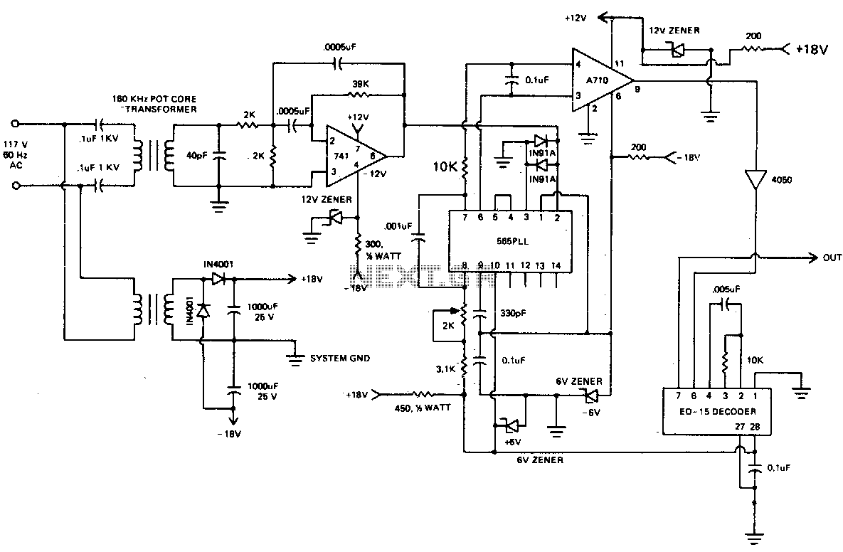
The 60 kHz transformer is designed for efficient energy transfer at high frequencies, making it suitable for applications in power electronics, signal processing, and RF circuits. The choice of an ungapped pot core allows for improved magnetic coupling and reduced losses, which is critical in high-frequency operations. The use of type "F" magnetic material enhances the core's performance by providing low core losses and high saturation flux density, ensuring reliable operation within the specified frequency range.
The winding configuration, with SOV2 turns for the secondary and a calculated number of turns for the primary, is essential for achieving the desired voltage transformation. The turns ratio of approximately 15:1 indicates that the primary winding has 15 times more turns than the secondary winding, which allows for stepping down the voltage efficiently. This transformer can be used in various applications, including power supplies, inverters, and signal isolation, where voltage transformation and impedance matching are required.
In designing the circuit around this transformer, attention must be given to the selection of components that can handle the operating frequency and the corresponding power levels. Proper insulation and thermal management should also be considered to ensure optimal performance and longevity of the transformer in its intended application.60 kHz transformer consists of a 18 x 11mm ungapped pot core (Siemens, Fer-rocube, etc), utilizing magnetics incorporated type "F" material wound with SOV2 turns of No5 wire for the secondary and turns for the primary This gives a turns ratio of approximately 15 to 1. 🔗 External reference
Related Circuits
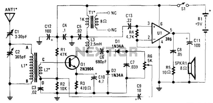
The RF signal is transmitted from the antenna through CI to a tuned circuit consisting of LI and C2. One end of L2 delivers the RF signal to the base of Q1 for amplification, while the other end connects...
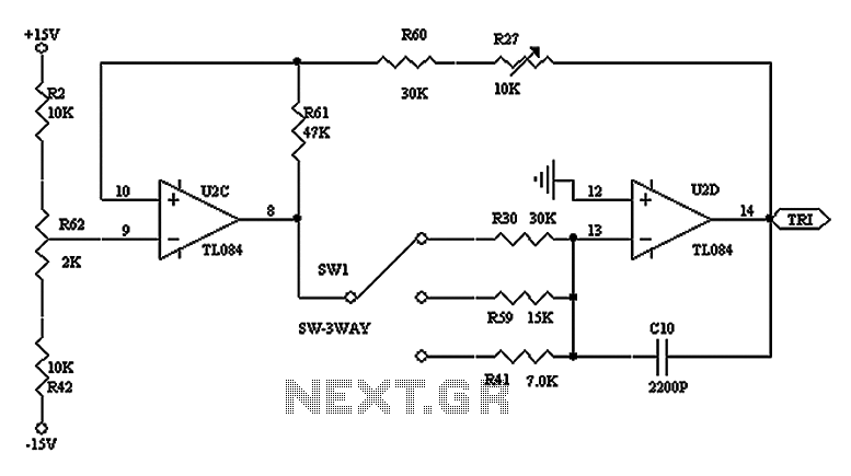
The triangular wave circuit consists of two operational amplifiers (OPs). R62 serves as the offset adjustment, while R27 is utilized for peak adjustment. A switch is included to select different resistances, allowing for the generation of triangular waves at...
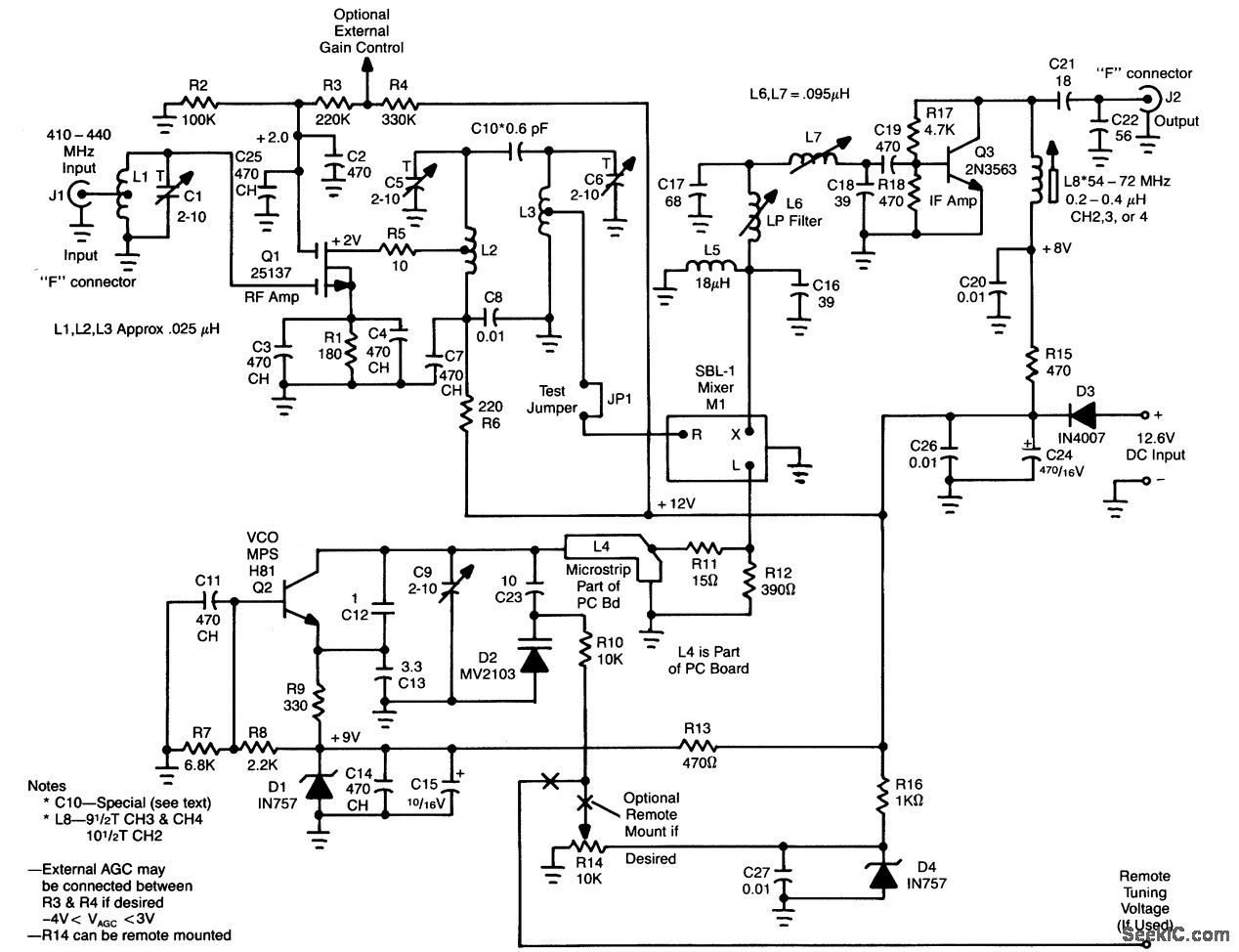
L1, Q1, L2, and L3 form an RF amplifier stage that drives M1, a doubly balanced mixer. Q4 serves as a local oscillator stage operating in the 375-MHz range. Signals in the 420 to 450-MHz range from Q1 are...
This page features H-Bridge circuits used for controlling direct current motors. Several designs are shown using both CMOS and Bi-Polar power devices. These circuits could be used as the basis for Model Railroad DCC Boosters or PWM motor controllers....
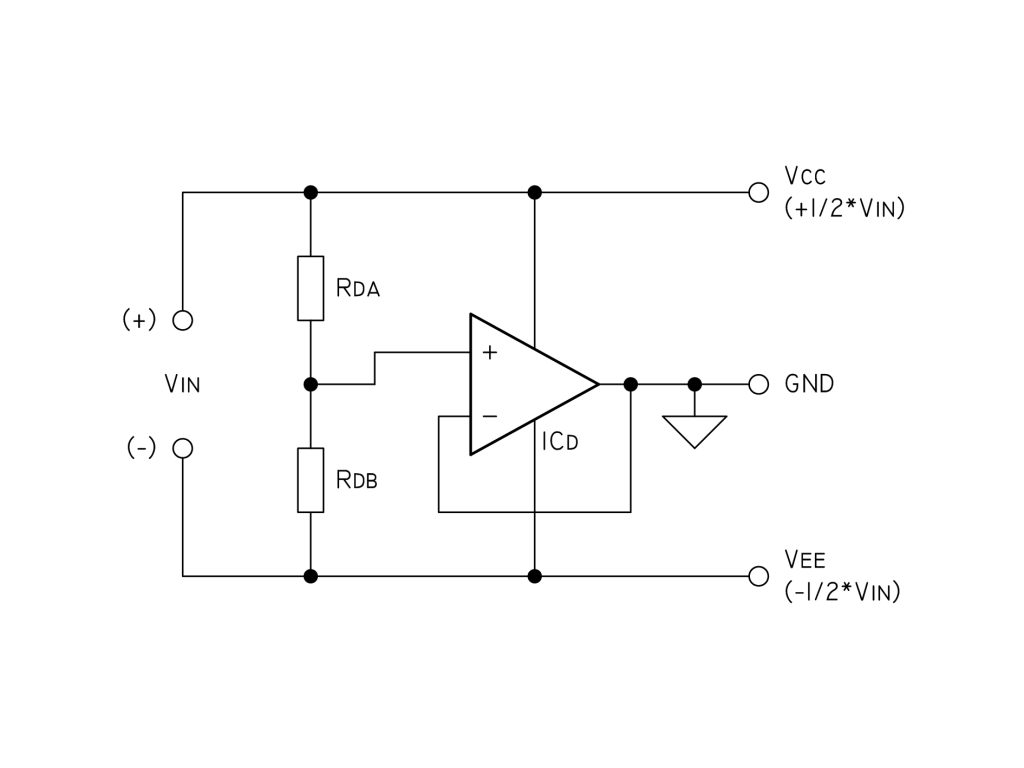
To eliminate noise, a 100µF capacitor and a 100nF bypass capacitor are used across the supply, along with two 10nF capacitors in parallel with the resistors Rda and Rdb (each 10K). For current limiting, a 22K resistor is paralleled...
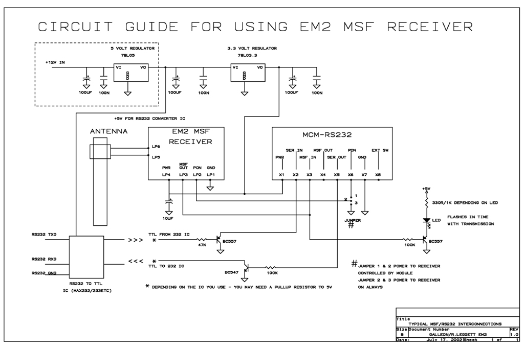
Instructions for utilizing the Galleon System modules to construct a radio time receiver designed to capture the 60 kHz MSF time signal emitted from the atomic clock located in Anthorn, Cumbria. The Galleon System modules offer a versatile platform for...