
Cassette-interface
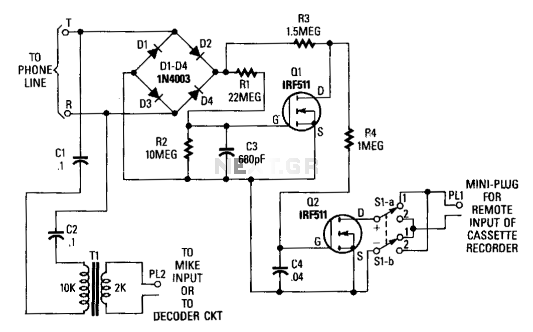
Q1 and Q2 form the foundation of an interface circuit that connects a cassette recorder to a telephone line. This circuit operates without an external power supply, drawing its power directly from the telephone line. The incoming signal is processed through a bridge rectifier circuit composed of diodes D1 to D4. When the phone is on-hook, the voltage at the output of the bridge at the R1/R3 junction is approximately 48 V. This voltage is then applied to a voltage divider consisting of resistors R1 and R2. The voltage at the junction of R1 and R2 is supplied to the gate of Q1, activating it and pulling the drain of Q1 low. As a result, the gate of Q2, which is connected to the drain of Q1, receives a low bias, keeping Q2 in the OFF state. When an answering machine answers a call or the phone is taken off-hook, the voltage across the phone lines drops below 10 V, causing Q1 to turn off. Consequently, the voltage at the drain of Q1 increases, turning Q2 on. The remote input of the cassette recorder is linked to the drain and source of Q2 via switch S1, with a miniature plug connected to the remote input jack. Switch S1 must be positioned so that the positive lead of the recorder's remote input connects, through switch position 1, to the drain of Q2, while the negative input connects to the source of Q2. This switch provides a practical method to reverse the circuit's trigger output without the need for soldering or desoldering leads. The audio from the phone is coupled through capacitors C1, C2, and transformer T1 to the microphone input of the cassette recorder.
The circuit employs two transistors, Q1 and Q2, to manage the switching mechanism based on the state of the telephone line. Q1 acts as a control switch that is sensitive to the voltage levels present when the phone is in use. The voltage divider formed by resistors R1 and R2 is critical for establishing the gate voltage of Q1, ensuring it turns on under the correct conditions. The bridge rectifier diodes (D1-D4) convert the alternating current from the phone line into a direct current that powers the circuit.
When the phone is on-hook, the high voltage at the R1/R3 junction keeps Q1 activated. As Q1 turns on, it effectively pulls its drain low, which in turn influences Q2's gate voltage. Q2 remains off, preventing any signal from reaching the cassette recorder. This design allows for power-efficient operation since the circuit relies solely on the telephone line's voltage, eliminating the need for an external power supply.
The transition of Q1 to the off state, triggered by a drop in line voltage, allows Q2 to turn on, facilitating the connection of the cassette recorder to the phone line. The design of switch S1 is particularly noteworthy, as it allows for easy modification of the circuit's output without requiring physical alterations to the wiring. This enhances the usability of the interface circuit, making it adaptable for various recording situations.
The coupling capacitors C1 and C2, along with transformer T1, serve to filter and condition the audio signal from the phone line before it reaches the cassette recorder's microphone input. This ensures that the audio quality is preserved during the recording process. The entire circuit is designed to function seamlessly with standard telephone systems, making it a valuable tool for recording telephone conversations or messages directly onto a cassette.Q1 and Q2 are used to form the basis of an interface circuit for attaching a cassette recorder to the phone line. The circuit does not require a power supply because operating power is drawn from the telephone line itself.
The incoming signal is fed across a bridge-rectifier circuit, consisting of diodes D1 through D4. When the phone is on hook, the voltage at the output of the bridge at the Rl/R3 junction is near 48 V. That voltage is fed across a voltage divider consisting of R1 and R2. The voltage at the junction formed by R1 and R2 is fed to the gate of Q1, turning it on. That pulls the drain of Q1low. Since the gate of Q2 is connected to the drain of Q1, the bias applied to the gate of Q2 is low, holding it in the OFF state. When the answering machine responds to a call or a phone is taken off hook, the voltage across the phone lines drops below 10 V, causing Q1 to tum off.
At that point, the voltage at Q1 "s drain rises, turning Q2 on. The remote input of the cassette is connected to Q2"s drain and source through S1, and a miniature plug is connected to the remote input jack. Switch S1 must be in a position so that the positive lead of the recorder"s remote input connects, through switch position 1, to Q2"s drain and the negative input to Q2"s source.
Switch S1 provides a convenient way to reverse the circuit"s trigger output without having to unsolder and resolder leads. The phone"s audio is coupled through C 1, C2, and T1 to the microphone input of the cassette recorder.
🔗 External reference