
CD4017 IC For Automatic Room Lights Sensor
The CD4017 is a decade counter IC that can drive multiple outputs based on the input clock signal. In the context of an automatic room lights sensor, the circuit is designed to turn on lights when ambient light levels drop below a certain threshold, indicating that the room is dark.
The circuit typically comprises two LDRs arranged in a voltage divider configuration. As light levels change, the resistance of the LDRs varies, which in turn affects the voltage at the input of a comparator or an operational amplifier. This voltage is compared against a reference voltage to determine whether the lights should be activated.
When the ambient light is sufficient, the output of the comparator remains low, keeping the CD4017 inactive. However, as light levels decrease, the voltage at the comparator input drops below the reference voltage, triggering the comparator output to go high. This high output can be connected to the clock input of the CD4017, which then counts and activates the corresponding output pin connected to the lighting circuit.
The circuit may also include additional components such as resistors and capacitors to stabilize the operation and prevent false triggering due to transient light changes. A relay can be used to control higher voltage lights, ensuring safe operation within the circuit.
In summary, the CD4017-based automatic room lights sensor circuit utilizes LDRs to detect ambient light levels, activating lights automatically when needed, thereby enhancing convenience and energy efficiency.The following circuit shows about CD4017 IC For Automatic Room Lights Sensor Circuit Diagram. Features: has only one light sensor, using two LDRs .. 🔗 External reference
Related Circuits
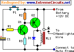
This device functions as a simple timer that keeps the vehicle's headlights on for approximately 1 minute and 30 seconds, allowing access to dark areas without the need to return and switch off the lights. Pressing switch P1 enables...
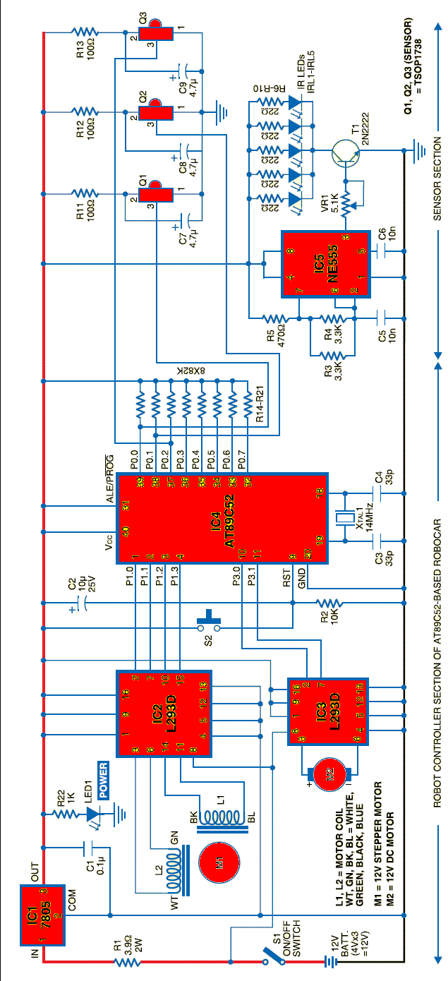
A robot can be defined as an electro-mechanical system with the capability of sensing its environment, manipulating it, and acting according to a preprogrammed sequence. It is a machine that... Robots are complex systems that integrate various components to perform tasks...

This example demonstrates a robust design featuring novelty lights that flash in a specific sequence, utilizing a 1-3-2-4 vault chase mode. The circuit includes diodes VD1 to VD4, which form a bridge rectifier, converting AC voltage to a full-wave...

This project utilizes the PIC18F25K20 microcontroller to detect changes in a sensor's state and emit sound from a speaker or piezo buzzer. The microcontroller also monitors the battery voltage during startup. The algorithm is straightforward, employing an interrupt-on-change mechanism...
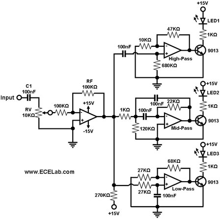
The simple circuit for converting an audio signal. The circuit basically consists of a buffer/amplifier stage and three filter circuits. The audio signal conversion circuit is designed to process audio signals efficiently while maintaining signal integrity. The circuit architecture includes...

This circuit differs from the standard 555 oscillator circuit by placing the LED in the capacitor reset line (pin 7). This configuration reduces overall current and prevents high peak LED current from draining the battery. The forward voltage drop...
Warning: include(partials/cookie-banner.php): Failed to open stream: Permission denied in /var/www/html/nextgr/view-circuit.php on line 713
Warning: include(): Failed opening 'partials/cookie-banner.php' for inclusion (include_path='.:/usr/share/php') in /var/www/html/nextgr/view-circuit.php on line 713