
Cell Phone Controlled Home Appliance circuit
The described circuit enables remote control of home appliances through a standard cell phone interface, leveraging the DTMF signaling method. The integration of a 0.1µF capacitor ensures proper filtering and signal integrity when interfacing the headphone output with the circuit. The ULN2803 serves as a crucial component, functioning as a Darlington driver that allows low-voltage signals from the DTMF decoder to control higher voltage relays without the need for additional components, thus optimizing space and enhancing performance.
In this setup, the DTMF decoder IC decodes the dual-tone signals generated by the phone keypad into a binary output. The 4x16 decoder IC expands the binary output to control multiple relays, effectively allowing the user to operate various appliances based on the keypresses. The D flip-flops act as memory elements, ensuring that the state of each relay is maintained until the next key press, providing a stable control mechanism.
The DTMF tones are generated by the phone in a specific pattern, where each key press corresponds to a unique combination of frequencies. The arrangement of the keypad into rows and columns allows for efficient detection of the pressed key, as each key generates a distinct pair of tones that can be easily identified by the DTMF decoder.
Overall, this circuit design exemplifies an innovative approach to home automation, utilizing readily available technology in smartphones to create a versatile control system for various appliances. The combination of DTMF technology, efficient circuit design, and the use of common electronic components makes this project both practical and accessible for users looking to enhance their home automation capabilities.Ever Imagined controlling your home appliances using your cell phone. You can find a lot of circuits for this application. But they make use of Telephone. I modified the circuit and redesigned it to make it compatible with normal cell phone headphone. Just connect the your phone headphone jack to the phone and the connections to the circuit as sho wn in the circuit. The relays are connected using the resistor and transistor. Use ULN2803 to reduce the circuit size and increase the performance. The connections from the output of flip-flops has to be given to the inputs of the buffer and relays has to be connected to the buffer. Normally the tip of the headset is connected to the circuit to the 0. 1uF capacitor as shown in the circuit diagram. The ground pin of headphone is connected to the ground of the circuit. When you press keys in your Phone, the other person will hear some tones with respect to keys pressed.
This tones are based on the DTMF technology. Data is transmitted in terms of pair of tones. The receiver detects the valid pair and gives the appropriate BCD code as the output of the DTMF decoder IC. The output of the DTMF IC is given to the 4x16 decoder IC. We have 12 signals possible because we have 12 keys (including * and #) in mobile keypad. The decoder are outputs are then given to D flip-flops. The outputs toggle whenever a key is pressed. In DTMF there are 16 distinct tones. Each tone is the sum of two frequencies: one from a low and one from a high frequency group. There are four different frequencies in each group. Your phone only uses 12 of the possible 16 tones. If you look at your phone, there are only 4 rows (R1, R2, R3 and R4) and 3 columns (C1, C2 and C3). The rows and columns select frequencies from the low and high frequency group respectively. The exact value of the frequencies are listed in Table 3 below: 🔗 External reference
Related Circuits
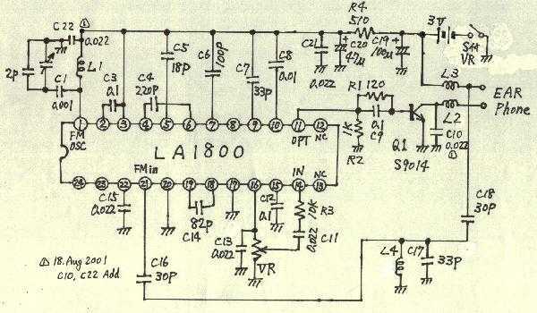
Earphones, batteries are sold separately. AM / FM seems to be a common mold. But stamping is different. AM / FM E193577 UL94V0 board with the AM / FM etching printed circuit board manufacturers are the same. Shape is...
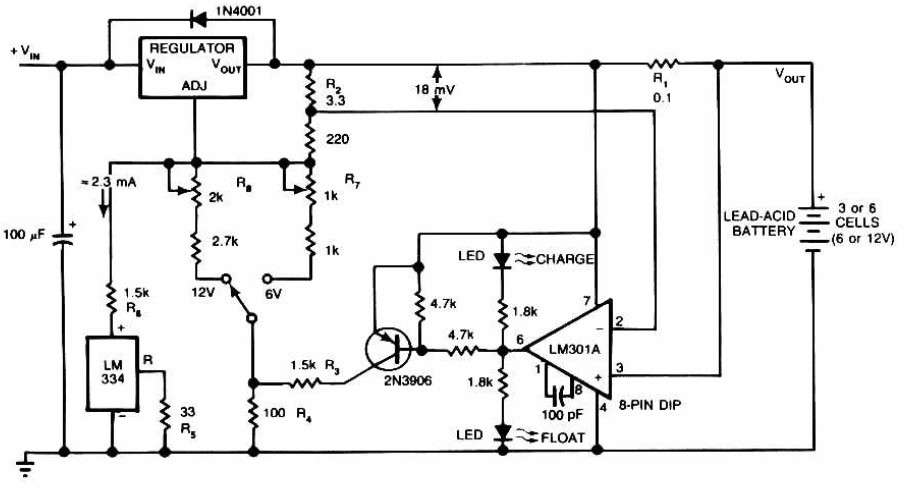
Lead-Acid Battery Charger circuit diagram. The LM301A compares the voltage drop across R1 with an 18 mV reference set by R2. The comparator's output controls the voltage regulator, forcing it to produce the lower float voltage when the battery-charging...
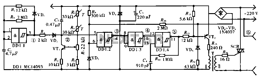
The circuit operates using a temperature stabilizer derived from the main oscillator (DD1.1), along with components including C1, R1, R2, and VD1. It incorporates a monostable multivibrator formed by R3, VD2, VT1, C2, R4, DD1.2, R7, and R8, as...
There are many variations in definitions of what exactly constitutes a robot. Consequently, it can be challenging to compare the number of robots across different countries. To provide a universally acceptable definition, the International Organization for Standardization (ISO) defines...
The core component of this DIY metal detector circuit is the CS209A. The metal detector is constructed with a single coil of 100 µH. The CS209A contains an oscillator that forms an LC circuit; the inductance of the coil...
This is the simplest VU meter that can be constructed. It is based on a single integrated circuit. A volume unit (VU) meter, or standard volume indicator, is a device used to display the level of any voltage signal...