
cell phone signal activated led
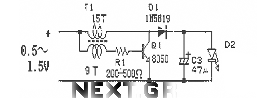
This cell phone signal-activated LED circuit utilizes a basic principle of detecting the radio frequency (RF) signals emitted by a mobile phone during an incoming call. The circuit typically consists of a few essential components: an RF receiver module, a microcontroller or a transistor for signal processing, and an LED for visual indication.
The RF receiver module is designed to pick up the specific frequency that mobile phones operate on. When a call is initiated, the RF receiver detects the signal and generates a corresponding output. This output can be used to trigger a transistor or microcontroller, which acts as a switch to control the LED.
The LED is connected in series with a current-limiting resistor to prevent excess current from damaging it. When the RF receiver detects the incoming call signal, it activates the transistor or microcontroller, allowing current to flow through the LED, thus lighting it up.
Power for the circuit can be supplied from a battery or an external power source, depending on the design requirements. Proper grounding and circuit protection should also be considered to ensure the reliability and longevity of the circuit.
This project serves as an excellent introduction to basic electronics and RF signal detection, demonstrating how everyday technology can be integrated into simple electronic circuits.A very simple and interesting project / schematic of a cell phone signal activated LED circuit. The circuit will light up an led when you call from your cell phone.. 🔗 External reference
Related Circuits

This LED thermometer is designed for home use, capable of reading temperatures between approximately 60 and 78 degrees Fahrenheit. It utilizes a precision temperature sensor IC, the LM34DZ, which requires no calibration and can measure temperatures ranging from -50°F...

This stroboscope circuit employs 16 high-brightness white LEDs housed in a torch and provides a signal output to a frequency counter for rev counter display. The circuit utilizes IC1, a 555 astable multivibrator, which generates a signal for IC2,...

This digital thermometer indicates the temperature measured with an NTC using 7 LEDs. The circuit works using an opamp, the well-known 741, which amplifies the voltage difference between its plus and minus input. This amplification (sensitivity) can be set...
The circuit indicates that the phone is in use by illuminating a red LED. When the phone is not in use, a green LED lights up. It operates without requiring external power and can be connected at any point...
This is a simple and easy-to-build DC-DC driver circuit designed for a single flashlight battery, operating at a parametric voltage of 1.5V. The input current is 90mA, while the light-emitting diode (LED) current is 26mA or higher. The circuit...

A voltage-controlled oscillator using the NE555. This circuit is commonly referred to as a voltage-to-frequency converter because the output frequency is altered by varying the input voltage. As previously noted, pin 5 serves as the voltage control terminal, which...
Warning: include(partials/cookie-banner.php): Failed to open stream: Permission denied in /var/www/html/nextgr/view-circuit.php on line 713
Warning: include(): Failed opening 'partials/cookie-banner.php' for inclusion (include_path='.:/usr/share/php') in /var/www/html/nextgr/view-circuit.php on line 713