
Central-image-canceller
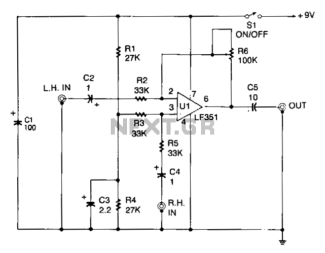
The circuit is designed to eliminate the vocal portion of an audio signal while preserving the instrumental portion. It achieves this by mixing two channels that are 180° out of phase, allowing the signals that create the center-stereo image to be canceled out. Typically, these signals are in phase. Resistor R3 biases the non-inverting input of U1 from a center tap created by resistors R1 and R4, along with capacitor C3. Resistor R4, capacitor C3, and potentiometer R6 form a negative feedback circuit that sets the closed-loop voltage gain of U1 to unity. The signal is inverted between the input and output. Signals applied to the right input are coupled to the non-inverting input of U1 through capacitor C4 and the attenuating resistor R5. Resistors R3 and R5 create a 6 dB attenuator, ensuring that there is unity voltage gain between the input and output. However, the right input signal remains non-inverted. Consequently, a signal present at both inputs is phased out by the circuit and will not appear at the output. Even if the two input signals differ slightly in levels due to varying source impedances, full cancellation can still be achieved by carefully adjusting R6.
The circuit operates by utilizing a differential amplifier configuration, where the phase relationship between the two audio channels is critical for achieving vocal cancellation. The 180° phase shift is accomplished by ensuring that one channel is inverted relative to the other. This is facilitated by the operational amplifier U1, which serves as the core of the circuit. The biasing of the non-inverting input through R3 ensures that the amplifier operates within its linear range, preventing distortion of the audio signal.
The negative feedback loop formed by R4, C3, and R6 stabilizes the gain of the operational amplifier at unity, which is essential for maintaining the integrity of the audio signal while preventing amplification of unwanted noise. The use of a potentiometer (R6) allows for fine-tuning of the circuit, enabling the user to adjust the gain precisely and achieve optimal vocal cancellation, even in the presence of variations in input signal levels.
Capacitor C4 serves to couple the right input signal to the non-inverting input of U1 while simultaneously blocking any DC offset that may be present, ensuring that only the AC audio signal is processed. Resistor R5, in conjunction with R3, forms a 6 dB attenuator, which reduces the amplitude of the right input signal to match the level of the inverted left input signal, thereby facilitating effective cancellation at the output.
In summary, this circuit is an effective solution for vocal removal in audio processing applications, leveraging phase cancellation techniques and precise component selection to achieve high-quality audio output while minimizing vocal presence. The ability to adjust the feedback and attenuation parameters ensures versatility in various audio environments.The circuit allows you to eliminate the vocal portion of an audio signal, while leaving the instru mental portion. The circuit mixes two channels that must be 180° out of phase, so the signals that form the center-stereo image is canceled out.
Those signals usually appear in phase. Resistor R3 biases the noninverting input of Ul from a center tap formed by resistors Rl and R4, and capacitor C3. Resistor R4, capacitor C3, and potentiometer R6 form a negative-feedback circuit that establishes the closed-loop voltage gain of Ul at unity.
The signal is inverted between the input and output. Signals applied to the right input are coupled to the noninverting input of Ul through C4 and attenuating resistor R5. Resistors R3 and R5 make up a 6 dB attenuator, so once again, there is unity voltage gain between the input and the output.
However, the right input signal is not inverted. Therefore, a signal appearing at both inputs is phased out by the circuit and will not appear at the output. Even if the two input signals are at slightly different levels because of different source impedances, you can still adjust for full cancellation by carefully tweaking R6.
🔗 External reference