
Charge amplifier
Charge amplifiers serve a critical role in converting charge signals from sensors into usable voltage levels, particularly in applications where precision and low noise are paramount. The core operation of a charge amplifier relies on its high input impedance, which minimizes the loading effect on the sensor output. This is particularly important in applications involving piezoelectric sensors, where the generated charge is often very small.
The architecture of a typical charge amplifier includes an operational amplifier (op-amp) configured with a feedback capacitor. The charge from the sensor is fed into the inverting input of the op-amp, while the feedback capacitor is connected between the output and the inverting input. This configuration allows the charge amplifier to produce an output voltage that is directly proportional to the input charge, with the relationship defined by the formula V_out = -Q_in / C_f, where V_out is the output voltage, Q_in is the input charge, and C_f is the feedback capacitance.
In practical applications, charge amplifiers are designed to have low noise characteristics, which is essential for accurate measurements in environments with minimal signal levels. The choice of components, such as the op-amp and feedback capacitor, is crucial in optimizing performance, including bandwidth and stability. Additionally, charge amplifiers are often integrated into more complex systems, such as those used in imaging technologies, where they must accommodate the high capacitance of circuit tracks without compromising the integrity of the signal from the sensor.
Overall, the design and implementation of charge amplifiers are fundamental in fields such as biomedical instrumentation, industrial automation, and scientific research, where the accurate conversion of charge to voltage is essential for data acquisition and analysis.A charge amplifier is an amplifier whose equivalent input impedance is a capacitive reactance that is very high at low frequencies. Thus contrary to what its name may suggest, a charge amplifier does not amplify the electric charge present at its input.
Its function is actually to obtain a voltage proportional to that charge and yield a low output impedance. Hence it is a charge-to-voltage converter. Common applications include piezoelectric sensors and photodiodes, in which the charge output from the transducer is converted into a voltage. Charge amplifiers are often found in instrumentation, and in the readout circuitry of CCD imagers and flat-panel X-ray detector arrays.
In read-out circuits the objective is usually to measure the very small charge stored within an in-pixel capacitor, despite the capacitance of the circuit-track to the readout circuit being a couple of orders of magnitude greater than the in-pixel capacitor. Gain is dependent only on the feedback capacitor, unlike voltage amplifiers, which are affected greatly by the input capacitance of the amplifier and the parallel capacitance of the cable [1] [2]
🔗 External reference
Related Circuits
The NCP5810D is a dual-output DC/DC converter capable of generating both positive and negative voltages. This device is optimized for powering modules such as AMOLED display drivers, where high output voltage accuracy, regulation, signal integrity, and compact design are...
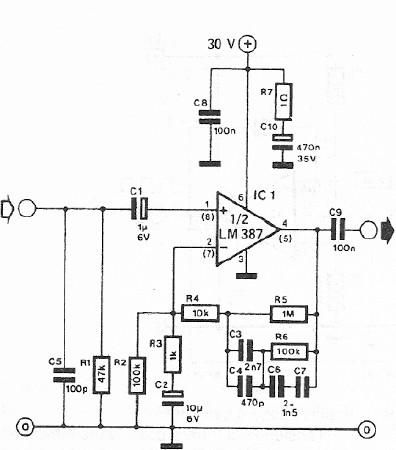
A dynamic microphone preamplifier can be constructed using the LM387 dual operational amplifier integrated circuit. The input impedance is approximately 47k ohms, primarily determined by resistor R1. If a dynamic microphone with a different impedance is to be connected,...
To complement the 60 Watt MOSFET audio amplifier, a high-quality preamplifier design was necessary. A discrete component topology, utilizing +24V and -24V supply rails, was selected, minimizing the transistor count while ensuring low noise, very low distortion, and a...
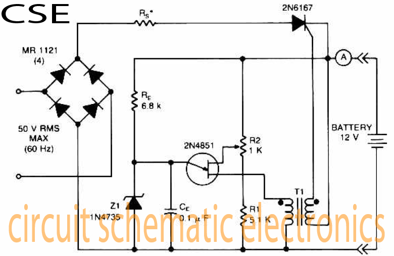
The accumulator charger circuit must provide a voltage that matches the specifications of the batteries being charged. For a 12-volt accumulator, the output voltage should not exceed 12 volts, nor should it fall significantly below this threshold. Failure to...
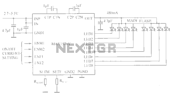
The circuit utilizes the MAX1576Y charge pump white LED driver, capable of supplying a total current of up to 480mA across two groups (n = 4 white LEDs). Each white LED in the flashing group can draw a maximum...
Figure 1 shows the circuit. A major change from all of the designs from that era is the speaker coupling capacitor - 1000uF (for a -3dB of 20Hz and a 8 Ohm load) was the most common value. This is...
Warning: include(partials/cookie-banner.php): Failed to open stream: Permission denied in /var/www/html/nextgr/view-circuit.php on line 713
Warning: include(): Failed opening 'partials/cookie-banner.php' for inclusion (include_path='.:/usr/share/php') in /var/www/html/nextgr/view-circuit.php on line 713