
Charger circuit V
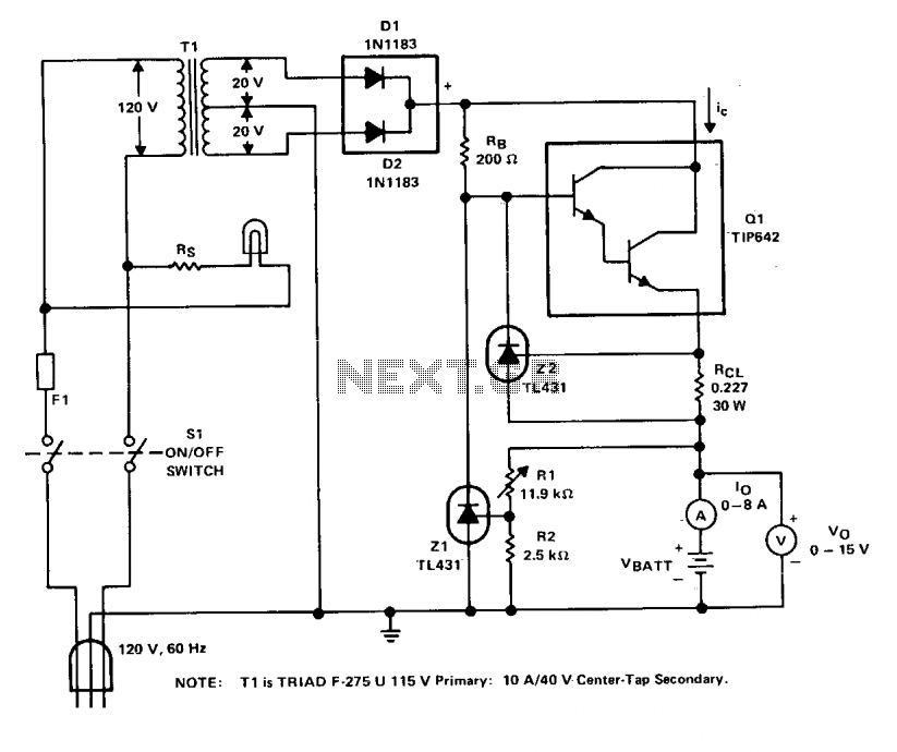
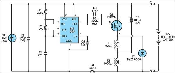
The charger circuit is designed to efficiently manage the charging process of lead-acid batteries while ensuring the safety and longevity of both the charger and the battery. The charging voltage of 14.4 V is specifically chosen to optimize the charging process for six series-connected cells, each rated at 2.4 V. By operating at a frequency of 120 Hz, the circuit effectively delivers energy in controlled pulses, which helps to minimize heat generation and prolongs the life of the battery.
The current limiting feature is a critical aspect of the design, as it prevents excessive current from flowing into the battery, which can lead to overheating and potential damage. This is particularly important for lead-acid batteries that may be in a deeply discharged state, where a high initial charging current could be detrimental. The specification of charging at one-fourth the ampere-hour rating ensures that the charging process is gentle enough to safely restore the battery's charge without causing harm.
In practical terms, for a battery with a capacity of 44 ampere-hours, the charger is configured to allow a maximum charging current of 11 A. This limit is crucial when the load impedance requires more current; the circuit's ability to enter a current limiting mode ensures that the charger can adapt to varying conditions without risking damage to its components or the battery itself. The regulation of the charging pulse amplitude to maintain an average current of 8 A further enhances the safety and efficiency of the charging process, ensuring that the battery is charged effectively while minimizing the risk of overcurrent conditions.
Overall, this charger design exemplifies a well-thought-out approach to battery management, balancing efficiency, safety, and adherence to manufacturer guidelines.The charger is based on a charging voltage of 2.4 V per cell, in accordance with most manufacturers' recommendations. The circuit pulses the battery under charge with 14.4 V (6 cells ? 2.4 V per cell) at a rate of 120 Hz. The design provides current limiting to protect the charger's internal components while limiting the charging rate to prevent damaging severely discharged lead-acid batteries.
The maximum recommended charging current is normally about one-fourth the ampere-hour rating of the battery. For example, the maximum charging current for an average 44 ampere-hour battery is 11 A. If the impedance of the load requires a charging current greater than the 11 A current limit, the circuit will go into current limiting. The amplitude of the charging pulses is controlled to maintain a maximum peak charging current of 11 A (8 A average).
🔗 External reference
Related Circuits
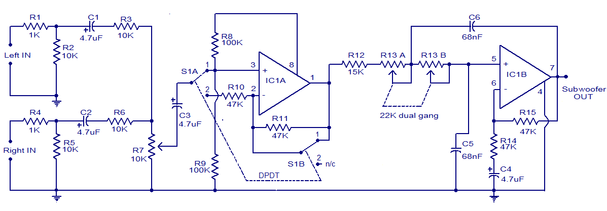
The circuit diagram depicts a simple subwoofer filter that operates on a 12V DC supply, making it particularly useful for automobile subwoofer applications. This circuit functions as a low-pass filter, with an adjustable pass frequency ranging from 60 to...
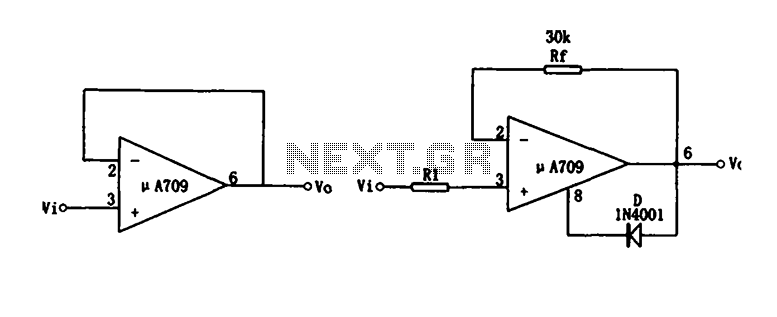
Figure (a) illustrates a voltage follower circuit, which serves as a specific instance of an in-phase amplifying circuit. The input signal originates from an integrated operational amplifier. At the conclusion of the introduction phase, the feedback resistor is set...

This is a simple and low-cost NiCd and NiMH battery charger. The schematic diagram indicates that the charging current (I) should be set to 1/10 of the battery's rated capacity. For instance, if the battery has a rated capacity...
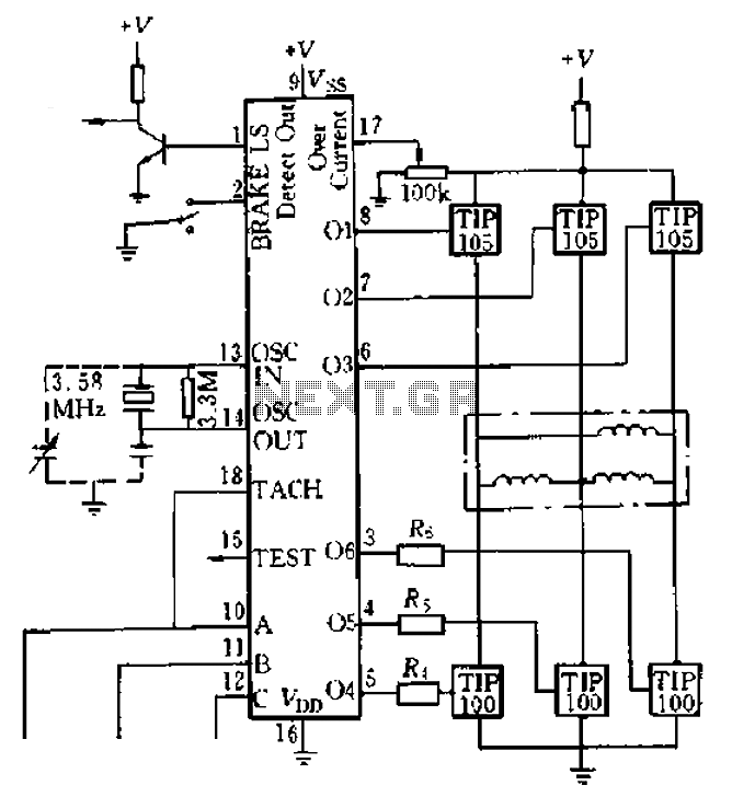
Four application examples are presented in the figure, focusing on a three-phase brushless DC motor used in Winchester disk drives with an operating speed of 3600 RPM. Although the original design specifies an operating speed of 3600 RPM, alternative...
The following circuit illustrates a 6/12/24V Lead Acid Battery Charger Circuit Diagram. Features: It is essentially a high-voltage pulse generator. The circuit diagram for a 6/12/24V Lead Acid Battery Charger is designed to efficiently charge lead-acid batteries of varying voltages....
All of the components in this list are generally available through RadioShack for less than $20. It is highly recommended to use a breadboard for assembly, as mistakes are common for first-time builders, and soldering can complicate troubleshooting. This...
Warning: include(partials/cookie-banner.php): Failed to open stream: Permission denied in /var/www/html/nextgr/view-circuit.php on line 713
Warning: include(): Failed opening 'partials/cookie-banner.php' for inclusion (include_path='.:/usr/share/php') in /var/www/html/nextgr/view-circuit.php on line 713