
Chase circuit loop type lights
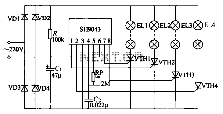
The circuit operates as follows: the bridge rectifier, constructed from diodes VD1 to VD4, converts the incoming AC voltage to a DC voltage suitable for powering the lights. The current-limiting resistor Ri ensures that the current flowing to the SH9043 and the lights does not exceed safe operating levels, while capacitor Ci smooths out any voltage fluctuations, providing a stable input for the integrated circuit.
The SH9043 serves as the heart of the control system, generating the timing signals necessary for the light sequence. The external components, potentiometer RP and capacitor C2, allow for fine-tuning of the oscillator frequency, which directly influences the chase rate of the lights. By adjusting RP, the user can modify the timing of the sequence, creating a dynamic visual effect.
The output from the SH9043 is connected to four thyristors (VTH1 to VTH4), which act as electronic switches. Each thyristor is responsible for controlling one of the lights (EL1 to EL4). When the SH9043 sends a trigger signal to a thyristor gate, it allows current to flow through the corresponding light, causing it to illuminate. This process creates the desired chase effect, with lights turning on and off in sequence.
Overall, this circuit design exemplifies the integration of basic electronic components to create an engaging visual display, suitable for various applications such as decorations or signaling devices. The adjustable parameters provide flexibility in operation, allowing customization of the light patterns to suit different preferences or requirements.This example is a particularly strong sense of jumping novelty lights, flashing its control order to take a 1 3-2-4 vault chase mode, the line shown. Diodes VD1-VD4 form a bridge rectifier circuit, the output of the full-wave rectified voltage lights as 4-way power,
through the current limiting resistor Ri and capacitor Ci after filtering SH9043 as an integrated circuit power. Potentiometer RP and capacitor c2 is SH9043 external resistor and capacitor adjustment RP can adjust the chip internal oscillator frequency, thus changing the vault chase rate four lights, flash frequency 1 ~ may vary between 200Hz.
IC O feet, feet, feet, feet respectively thyristor VTH2, VTH4, VTH1, VTH3 the gate contact. 4 output signals for controlling the thyristor or not. So that the series with the thyristor anode loop string lights EL1- ELA shine.
Related Circuits
This circuit is designed to detect whether the load of a battery charger or plug-in adapter is properly connected. The load may consist of a set of batteries needing charging or any other device that operates on low DC...

The circuit connection is illustrated in figures a and b. In figure a, a star-shaped winding is used with shunt capacitance, while figure b depicts a triangular winding with capacitance connected in parallel. The working capacitance (Cc) is calculated...
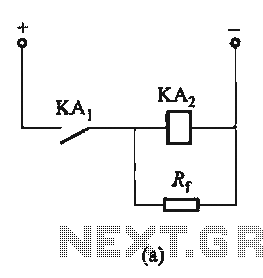
The circuit depicted in Figure 6-24 includes a relay coil with both ends connected in parallel to either a resistor Rf or an auxiliary diode VD. This configuration is equivalent to providing power after a short circuit, which increases...
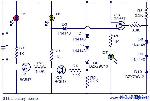
This is the circuit diagram of a 3 LED bar graph type battery monitor circuit that is ideal for monitoring the voltage level of an automobile battery. When battery voltage is 11.5V or less, transistor Q1 will be on...
For several years, a rear fog lamp has been mandatory for trailers and caravans to enhance visibility in foggy conditions. When the fog lamp is activated, the fog lamp of the towing vehicle must be turned off to prevent...
Due to the recent launch of Cranial Electrotherapy Stimulation (CES) portable devices in Europe, a similar circuit has been designed for hobbyists. CES is a widely used method for electrically enhancing brain function and has been prescribed by medical...
Warning: include(partials/cookie-banner.php): Failed to open stream: Permission denied in /var/www/html/nextgr/view-circuit.php on line 713
Warning: include(): Failed opening 'partials/cookie-banner.php' for inclusion (include_path='.:/usr/share/php') in /var/www/html/nextgr/view-circuit.php on line 713