
Circuit 3 LED battery monitor Schematic Diagram
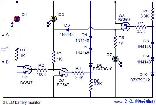
The circuit operates as a voltage level indicator for an automobile battery, utilizing three LEDs to represent different voltage ranges. The design employs three transistors (Q1, Q2, Q3) as switches that activate the corresponding LEDs based on the detected voltage level of the battery.
In detail, when the battery voltage falls to 11.5V or below, Q1 is activated, allowing current to flow through LED D1, which lights up to indicate a low battery condition. This serves as a warning to the user that the battery may need recharging or replacement.
For battery voltages ranging from 11.5V to 13.5V, Q2 is triggered, illuminating LED D2. This range indicates that the battery is in a moderate state, where it is neither fully charged nor critically low. It provides a visual cue for the user to monitor the battery's status.
When the battery voltage exceeds 13.5V, Q3 is turned on, and LED D3 lights up, indicating that the battery is sufficiently charged. This condition is typically associated with the battery being in a healthy state, especially when the engine is running and the alternator is charging the battery.
The circuit should be assembled on a general-purpose printed circuit board (PCB), which allows for easy integration of the components and ensures reliable connections. The battery to be monitored can be connected across terminals A and B, facilitating straightforward installation. Using LEDs of different colors for each voltage indicator enhances the visual distinction between the states, making it easier for users to interpret the battery condition at a glance.
Overall, this 3 LED bar graph battery monitor circuit provides a simple yet effective solution for monitoring automobile battery voltage levels, ensuring users can maintain their batteries in optimal condition.This is the circuit diagram of a 3 LED bar graph type battery monitor circuit that is ideal for monitoring the voltage level of an automobile battery. When battery voltage is 11. 5V or less transistor Q1 will be On and the LED D1 will be glowing. When battery voltage is between 11. 5 and 13. 5V, the transistor Q2 will be On and the LED D2 will be glowi ng. When battery voltage is above 13. 5V the transistor Q3 will be On and the LED D7 will be glowing. Assemble the circuit on a general purpose PCB. The battery to be monitored can be connected between the terminals namely A and B. It is always better to use LEDs of different colour. You are reading the Circuits of Circuit 3 LED battery monitor And this circuit permalink url it is 🔗 External reference
Related Circuits
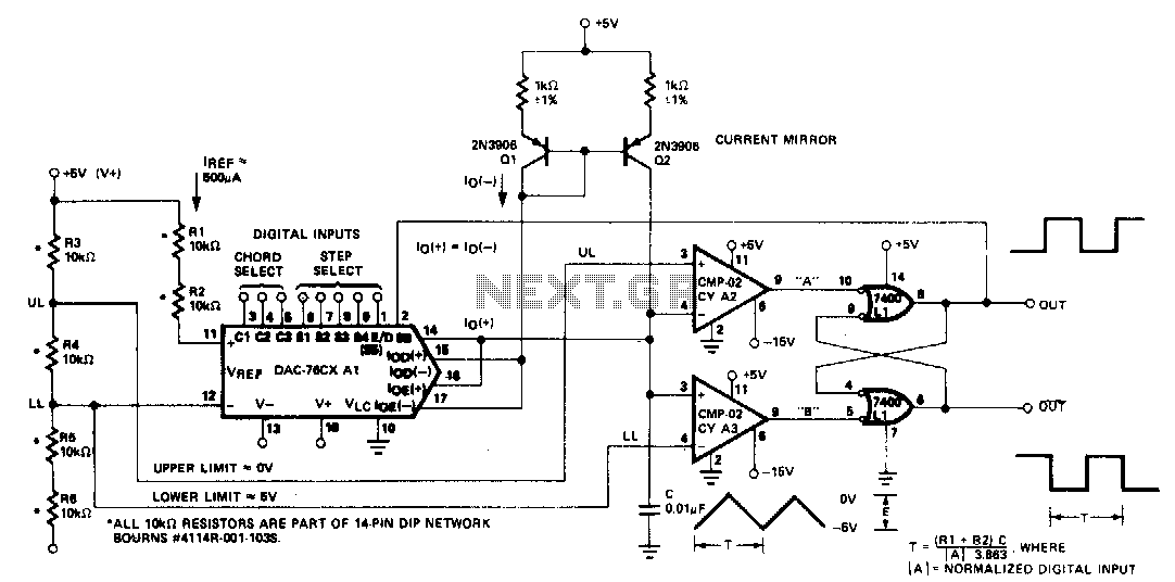
The microprocessor-controlled oscillator has a frequency range of 8159 to 1, covering from 2 Hz to 20 kHz. An exponential, current output integrated circuit digital-to-analog converter (DAC) functions as a programmable current source, alternately charging and discharging a capacitor...
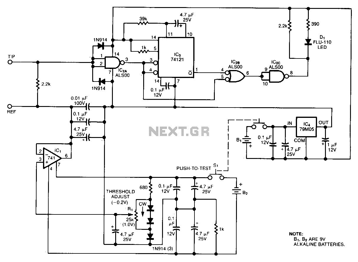
Oscilloscope measurements of ground noise can be unreliable because noise can enter your circuit via the scope's three-pronged power plug. This issue can be mitigated by utilizing the ground-noise tester described. The circuit operates on two 9-V batteries and...
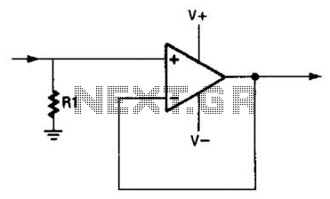
An operational amplifier (op amp) can function as a unity gain amplifier by connecting its output to its inverting input as illustrated. The load resistance (Rl) should be sufficiently low to prevent the op amp's bias current from introducing...
The oscillator employs a fundamental quartz crystal, capable of achieving an oscillation frequency of up to 10 MHz. The oscillator circuit is calibrated to the resonant frequency of the crystal. A capacitor, designated as C, with a value of...
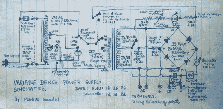
This power supply is able to deliver adjustable center-tapped DC from 0 to about 30 volts, as well as AC directly from the Variac and from the main transformer before the rectifier. What's primitive by today's standard is that...
A bridge rectifier capacitor filter serves as a primary power supply for current amplifier circuits. This power supply configuration is straightforward and offers enhanced performance. The bridge rectifier circuit is a full-wave rectifying circuit, meaning it converts both the...