
Circuits
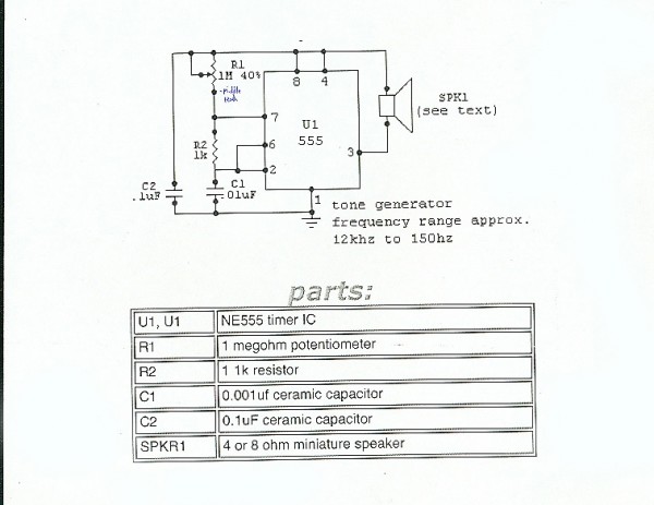
The circuit described involves a systematic approach to teaching fundamental electronics concepts, particularly focusing on the assembly of various components on a breadboard. The NE555 Timer IC serves as a pivotal component in the circuit, functioning as an astable multivibrator to produce sound. The connections begin with establishing the ground (GND) and Vcc pins, which are essential for powering the IC. The NE555 Timer is configured with resistors and capacitors to determine the frequency of oscillation, which in turn influences the tone produced.
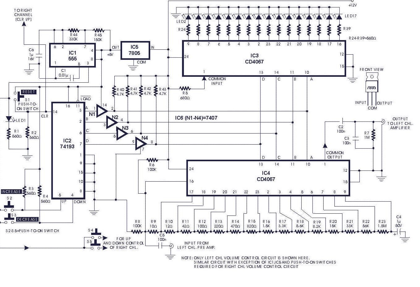
In the initial circuit, a nine-volt battery powers LEDs, each with a specified forward voltage and current. Ohm's Law is applied to determine the necessary resistance to prevent excess current from damaging the LEDs, ensuring they operate within safe limits. The use of alligator clips facilitates temporary connections, allowing students to experiment with circuit configurations easily.
The second circuit introduces a 12V DC power supply and an LM7805 voltage regulator, which is crucial for providing a stable 5V output to power the LEDs. The regulator's input voltage is reduced to a level suitable for the components, and students must calculate the appropriate resistance values for the LED to ensure optimal performance. This circuit emphasizes the importance of understanding voltage regulation and its application in electronic projects.
Overall, these exercises not only enhance students' practical skills in circuit assembly and soldering but also deepen their understanding of electronic principles, fostering a foundation for more advanced projects in digital fabrication and physical computing. The integration of hands-on learning with theoretical concepts prepares students for future endeavors in electronics and engineering.In order to avoid any soldering mistakes, I asked students to place all there resistors in the board first, and once I checked them, they could solder away. Capacitors were next, then LEDs then everything else. The middle school class had more success with putting the kits together quickly. Maybe soldering was more of a novelty for them They comp leted their boards within two classes, but the high school students had the potential to drag the process into a third class. Rather than do that, I finished all but one of the boards. There was one high school student who completed his Freeduino over the weekend and worked on the Proto Shield from Adafruit in class.
A few years back, I took a summer physical computing class at Parsons with Dan Mikesell. For our first circuit he gave us the following schematic and image to work with: I like this assignment because it introduces an IC chip, the NE555 Timer, and it makes an awful noise when it works. I also like it because initially it seems hard, but when students take a moment to think about the connections, it turns out to be quite simple.
I always tell students to start with the GND and Vcc pins and go from there. It`s like solving a puzzle. After displaying the schematic, I hand out a bag with the components. For each student, or group of students, I remove the components from the bag, name them, and describe their function. Then I leave students alone to figure out the wiring. Today was Middle School Physical Computing and it was the last class of the day. Everyone was exhausted, but we still managed to play with the LED Resistor Calculator and two students out of eight were able to generate annoying tones.
I also purchased the Makerbot CupCake CNC for school today. Makerbot describes the CupCake CNC as a rock solid open source 3D printer that is easy to build, easy to run, and easy to use. Its 100% open source, built to be hacked, and beginner friendly. The plan is to have the High School students research digital fabrication and then build the printer in November.
Very cool! So today we wired up our first circuits. Before class started I put together boxes for each student with a breadboard, LEDs and a voltage regulator. When students came into class, I handed them their boxes and placed wires, batteries, alligator clips, wire cutters and strippers in the center of the room.
Sitting on the floor, we started with nine volt batteries and LEDs with a forward voltage of 3V and a forward current of 0. 03A. After using Ohm`s Law to figure out the resistance, we selected resistors and used alligator clips to make connections and light the LEDs.
The second circuit included a breadboard, a 12V DC power supply, an LM7805 voltage regulator, an LED and a resistor. As students were less confident about wiring up the voltage regulator and figuring out the new resistance, this circuit took a bit longer to complete.
Forty-five minutes goes fast. Even though all the materials were prepared ahead of time, I didn`t get a chance to cover LED properties or the resistor values involved with illuminating an RGB LED in the way that I planned. No one had time to wire up the Piranhas, or High-Flux LEDs, and no one had a chance to clean up before running to their next class.
After spending the past summer gathering materials for my different classes, I thought it might be nice to share what I found inspiring, what I learned and how it all panned out. Over the year, I will write about my experiences teaching Physical Computing, IPhone programming, and 2D and 3D animation to kids.
I`ll try to explore what worked and what didn`t, what I would do again, and what I wouldn`t. I`ve learned so much from various people, books and websites, and I hope that by sharing my thoughts, successes and failures, I can give back to a community that I have gotten so much from. 🔗 External reference
Related Circuits
LM5576MHX absolute maximum ratings: (1) VIN to GND: 76V; (2) BST to GND: 90V; (3) PRE to GND: 76V; (4) SW to GND (Steady State): -1.5V; (5) BST to VCC: 76V; (6) SD, VCC to GND: 14V; (7) BST...
The machine model, commonly used for ESD testing in Japan, is a more severe ESD test. This model simulates metallic contact between the device under test and a charged body. The source capacitor is 200pF with no limiting resistor....
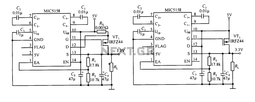
The circuit consists of peripheral components for the MIC5158, a linear regulator that converts a 5V input into a 3.3V output with a maximum current of 10A. When the input voltage (Ui) is 5V, an N-channel MOSFET, specifically the...
The gain of the single-stage virtual earth amplifier IC1 is determined by the drain-source resistance of the field-effect transistor (FET). Resistors R1, R2, and R3 linearize the FET's voltage-current characteristic. A control voltage is derived from the output signal...
This low noise audio power supply circuit can reduce noise and ripple voltage by 40 dB over the 100 Hz to 20 kHz audio range. In portable applications such as... This low noise audio power supply circuit is designed to...
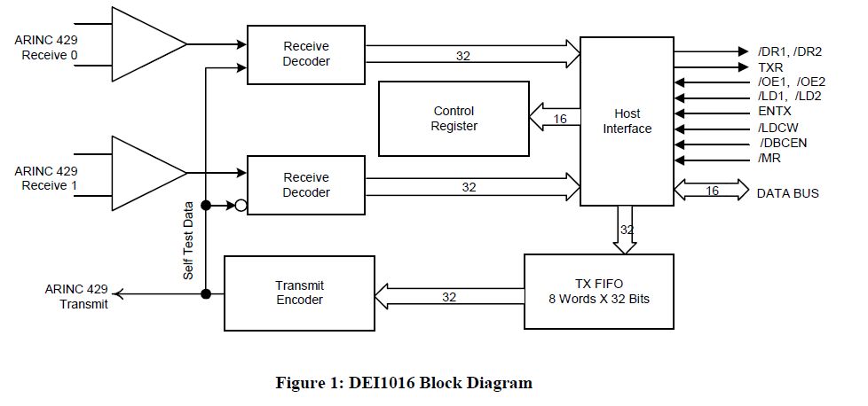
This document outlines the process of interfacing an Arduino with an ARINC 429 transceiver, illustrating the general methodology for connecting an Arduino to electronic circuits that can be applied to individual designs. The ARINC 429 bus is the predominant...