
Pressure Sensor Alarm Circuit Schematic

The simple pressure sensor alarm circuit consists of several key components: a 9V battery, a piezo sounder, a MOSFET (T1), an integrated circuit (IC1), and passive components such as resistors (R3) and capacitors (C2). The primary function of the circuit is to detect pressure changes via the piezo-ceramic wafer, which acts as a sensor. When pressure is applied to the wafer, it generates a voltage signal that is fed into the gate of the MOSFET T1. This signal turns on the MOSFET, allowing current to flow through the circuit and reactivating the integrated circuit IC1.
IC1 is responsible for controlling the output signal to the piezo sounder. The duration of the beep produced by the piezo sounder is influenced by the values of R3 and C2, which form an RC timing circuit. By adjusting these component values, the user can modify the beep duration to suit their preferences. Additionally, the piezo sounder can be replaced with a relay, which would enable the circuit to control larger loads or other devices, making this alarm system versatile for various applications.
The circuit's design allows for flexibility in component selection, as the values of T1, R3, and C2 are not strictly defined. This flexibility encourages experimentation, enabling users to tailor the circuit's performance to their specific needs. The availability of piezo sensors in the hobby electronics market further facilitates the assembly of this straightforward yet effective pressure sensor alarm system. Overall, this circuit exemplifies an accessible project for electronics enthusiasts, offering a practical application of pressure sensing technology.The simple pressure sensor alarm is built around a couple of readily available cheap components. Working of this circuit is straight forward and self-explanatory. When the circuit is powered by a 9V compact battery, the active piezo-sounder at the output of IC1 starts beeping for a short time and then goes into idle state. Whenever, the pressure sensor element (Piezo-ceramic wafer) is gently tapped, mosfet T1 is fired by the electric pulse from the sensor through related components and IC1 is again enabled by T1. As a result, the piezo-sounder starts beeping for a short duration, set by the in-circuit values of R3 and C2.
Piezo-sounder at the output of IC1 can be replaced with a low current 6 to 9 V electromagnetic/solid-state relay to control external loads. Likewise, values of components T1, R3 and C2 are not very critical. You can experiment with another values to tune the circuit as per your requirements. Pressure sensors (in piezo-wafer form) are widely available with reputed hobby electronics components dealers.
🔗 External reference
Related Circuits
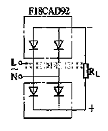
The circuit depicted is a single-phase bridge rectifier. It consists of arms with a cathode (negative electrode) and parallel anodes (positive electrodes) arranged in a configuration that connects multiple rectifier modules to form a bridge, commonly referred to as...
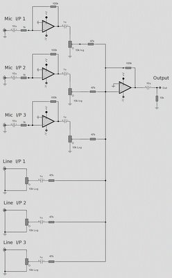
The microphone inputs are amplified approximately 100 times or 40 dB, with the total gain of the mixer, including the summing amplifier, reaching 46 dB. The microphone input is designed for microphones that produce an output of around 2...
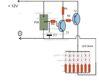
The circuit is an LED driver that responds to ambient light as well as the presence of an intruder, varying its illumination accordingly. Additionally, it includes an ambient light sensor to turn the LEDs on and off, and a...
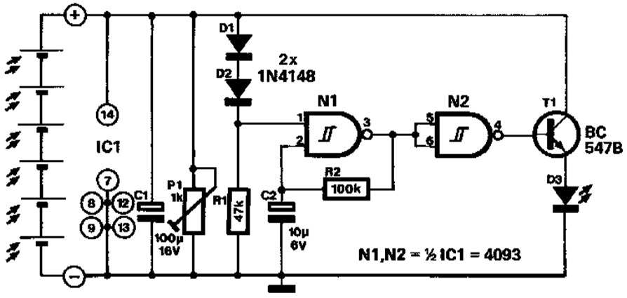
A novel application of solar cells simplifies the process of positioning a car in a garage, offering an improvement over traditional methods such as using old tires, mirrors, or chalk marks. The six solar cells depicted in Figure 1...
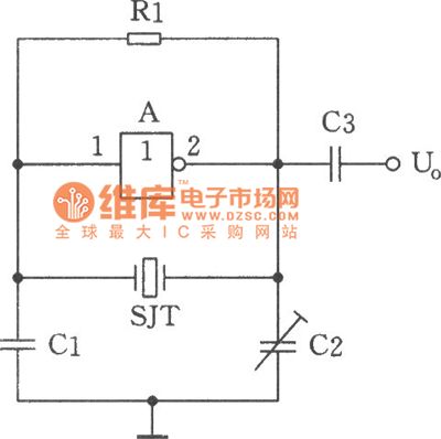
The image depicts a sine wave oscillator that consists of a quartz crystal (SJT) and gate A of the hex inverter IC CD4069. Compared to a standard RC phase-shift oscillator, the frequency stability of a crystal oscillator can achieve...
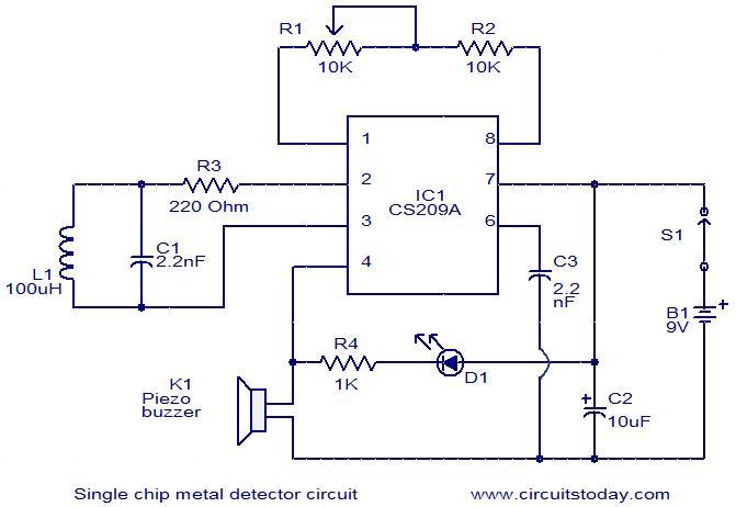
This is a simple single-chip metal detector circuit based on the IC CS209A from Cherry Semiconductors. A 100µH coil is utilized to detect the presence of metal. The IC CS209A incorporates a built-in oscillator circuit, with the coil (L1)...