


A simple phone automatic recording circuit
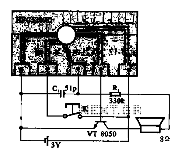
Description: A simple phone automatically displays the recording circuit. In this circuit, after the call, the Ming sound start switch K is activated by the sound of the automatic message HFC5209D.
The described circuit functions as an automatic call recording system integrated into a phone. Upon receiving an incoming call, the circuit is designed to activate a specific switch, referred to as switch K. This activation is triggered by the detection of a sound signal, specifically the "Ming" sound, which serves as an alert for the user.
The core component of this circuit is the HFC5209D, a message playback chip that plays the pre-recorded automatic message upon activation. This chip is capable of storing and reproducing audio data, making it suitable for applications requiring voice prompts or notifications.
The operational flow of the circuit begins when a call is received. The sound of the ringing phone generates the "Ming" sound, which is detected by a sound sensor or microphone integrated into the circuit. Once the sound is detected, it sends a signal to switch K, closing the circuit and powering the HFC5209D. The chip then plays the recorded message, indicating to the user that the call is being recorded.
Additional components may include a power supply circuit to provide the necessary voltage to the HFC5209D and any associated amplifiers needed to ensure the audio output is clear and audible. Furthermore, a recording medium, such as a memory chip or storage device, may be included to store the recorded calls for future playback.
In summary, this automatic recording circuit provides a seamless integration of sound detection and message playback, enhancing the functionality of the phone by ensuring that calls can be recorded and acknowledged through pre-defined audio prompts.A simple phone automatically shows the recording circuit. In this circuit, after the call Ming sound start switch K is turned on by the sound of automatic message HFC5209D.
The described circuit functions as an automatic call recording system integrated into a phone. Upon receiving an incoming call, the circuit is designed to activate a specific switch, referred to as switch K. This activation is triggered by the detection of a sound signal, specifically the "Ming" sound, which serves as an alert for the user.
The core component of this circuit is the HFC5209D, a message playback chip that plays the pre-recorded automatic message upon activation. This chip is capable of storing and reproducing audio data, making it suitable for applications requiring voice prompts or notifications.
The operational flow of the circuit begins when a call is received. The sound of the ringing phone generates the "Ming" sound, which is detected by a sound sensor or microphone integrated into the circuit. Once the sound is detected, it sends a signal to switch K, closing the circuit and powering the HFC5209D. The chip then plays the recorded message, indicating to the user that the call is being recorded.
Additional components may include a power supply circuit to provide the necessary voltage to the HFC5209D and any associated amplifiers needed to ensure the audio output is clear and audible. Furthermore, a recording medium, such as a memory chip or storage device, may be included to store the recorded calls for future playback.
In summary, this automatic recording circuit provides a seamless integration of sound detection and message playback, enhancing the functionality of the phone by ensuring that calls can be recorded and acknowledged through pre-defined audio prompts.A simple phone automatically shows the recording circuit. In this circuit, after the call Ming sound start switch K is turned on by the sound of automatic message HFC5209D.
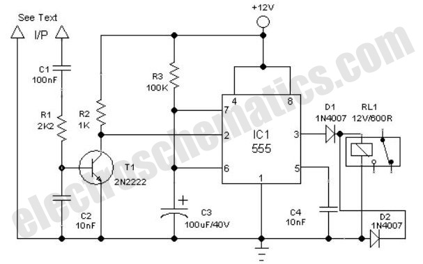
Clock Alarm Light Switch Circuit
This is a simple automatic light switch circuit designed for bedrooms. After construction, the input terminals of this circuit should be connected in parallel to the intended lighting fixture.
The automatic light switch circuit utilizes a light-dependent resistor (LDR) as the...

Quartz Controlled Bedroom Light Switch
This is a simple automatic light switch circuit designed for bedrooms. After construction, connect the input terminals of this circuit in parallel to the existing light fixture.
The automatic light switch circuit operates using a photoresistor (LDR) and a transistor as...
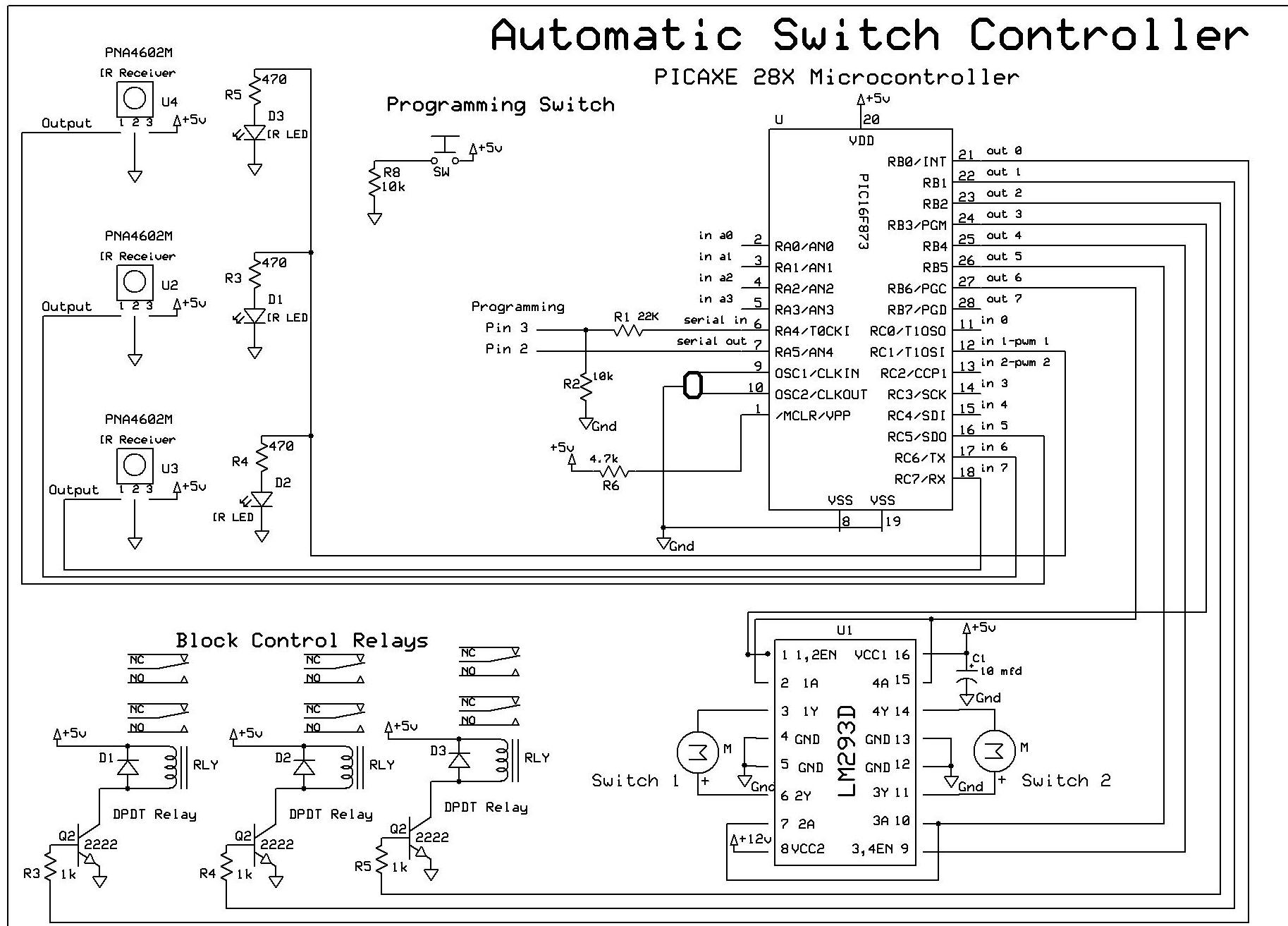
Automatic Switch Project
The objective of this controller project is to achieve automatic block and switch control for five separate engines operating on two independent loops of track. Each loop has both public and hidden sections. The inner loop accommodates three trains, while...