


Ac Wiring Locator Circuit
#ac wiring
#rectifier
#multivibrator
#555 timer
#piezoelectric speaker
#voltage detector
#safety
#current limiting
#half-wave rectifier
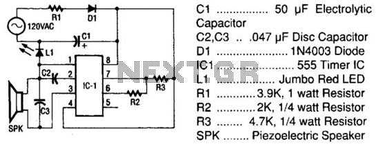
Description: The tester comprises a rectifier circuit and a multivibrator circuit. The alternating current (AC) voltage is half-wave rectified by diode D1 and stored in capacitor C1. Resistor R1 is employed to limit the current through D1 to a safe level. The voltage accumulated across C1 provides the operating power for IC1. The integrated circuit, a versatile 555 timer, is configured to function as a multivibrator, with its operating frequency determined by components C2, R2, and R3. The output from IC1, available at pin 3, is connected to a piezoelectric speaker (SPK), which signals the presence of AC. Additionally, an LED (L1) illuminates when AC is detected.
The circuit operates effectively by first converting the incoming AC voltage into a usable DC voltage through the half-wave rectification process. Diode D1 is crucial in this conversion, allowing current to flow in only one direction, thus preventing reverse current that could potentially damage other components. The current-limiting resistor R1 ensures that the diode operates within safe parameters, preventing excessive current flow that could lead to overheating or failure.
Capacitor C1 acts as a storage element, smoothing out the rectified voltage to provide a stable DC voltage to the 555 timer IC (IC1). The 555 timer is set up in astable mode, where it continuously oscillates between high and low states, generating a square wave output. The frequency of oscillation is determined by the values of resistors R2 and R3 in conjunction with capacitor C2. The specific values of these components can be adjusted to set the desired frequency of the output signal.
The output from pin 3 of the 555 timer is used to drive a piezoelectric speaker (SPK), which converts the electrical signal into sound waves, providing an audible indication of the presence of AC voltage. This feature is particularly useful in applications where visual indicators are not sufficient or practical.
In addition to the audio signal, the circuit includes an LED (L1) that serves as a visual indicator. When AC voltage is present, the LED lights up, providing a clear and immediate indication of voltage presence. This dual indication method—both auditory and visual—enhances the usability of the tester, making it effective in various applications where AC voltage detection is required.
Overall, this circuit design is compact and efficient, suitable for quick diagnostics and monitoring of AC voltage in various electronic and electrical systems. The tester consists of a rectifier circuit and a multivibrator circuit. The ac voltage is half-wave rectified by diode D1 and stored in capacitor CI. Resistor Rl is used to limit the current through D1 to a safe value. The voltage stored across CI supplies ICi operating power. The IC, the versatile 555 timer, is configured to operate as a multivibration whose operating frequency is determined by C2, R2, and R3. The output of ICI, on pin 3, is coupled to a piezoelectric speaker (SPK), which gives an indication of the presence of ac.
An LED (LI) also lights when ac is present.
The circuit operates effectively by first converting the incoming AC voltage into a usable DC voltage through the half-wave rectification process. Diode D1 is crucial in this conversion, allowing current to flow in only one direction, thus preventing reverse current that could potentially damage other components. The current-limiting resistor R1 ensures that the diode operates within safe parameters, preventing excessive current flow that could lead to overheating or failure.
Capacitor C1 acts as a storage element, smoothing out the rectified voltage to provide a stable DC voltage to the 555 timer IC (IC1). The 555 timer is set up in astable mode, where it continuously oscillates between high and low states, generating a square wave output. The frequency of oscillation is determined by the values of resistors R2 and R3 in conjunction with capacitor C2. The specific values of these components can be adjusted to set the desired frequency of the output signal.
The output from pin 3 of the 555 timer is used to drive a piezoelectric speaker (SPK), which converts the electrical signal into sound waves, providing an audible indication of the presence of AC voltage. This feature is particularly useful in applications where visual indicators are not sufficient or practical.
In addition to the audio signal, the circuit includes an LED (L1) that serves as a visual indicator. When AC voltage is present, the LED lights up, providing a clear and immediate indication of voltage presence. This dual indication method—both auditory and visual—enhances the usability of the tester, making it effective in various applications where AC voltage detection is required.
Overall, this circuit design is compact and efficient, suitable for quick diagnostics and monitoring of AC voltage in various electronic and electrical systems. The tester consists of a rectifier circuit and a multivibrator circuit. The ac voltage is half-wave rectified by diode D1 and stored in capacitor CI. Resistor Rl is used to limit the current through D1 to a safe value. The voltage stored across CI supplies ICi operating power. The IC, the versatile 555 timer, is configured to operate as a multivibration whose operating frequency is determined by C2, R2, and R3. The output of ICI, on pin 3, is coupled to a piezoelectric speaker (SPK), which gives an indication of the presence of ac.
An LED (LI) also lights when ac is present.

Astable Multivibrator Ii Circuit
An astable multivibrator based on the 555 timer is presented. The frequency is approximately 975 Hz, determined by the values of RB and C.
The astable multivibrator configuration using the 555 timer is a popular circuit for generating square wave signals....

555 ramp generator
The voltage rating of the 470 µF capacitor is not critical, provided it significantly exceeds the maximum power supply voltage, which is 12 volts in this circuit. It is essential to connect this capacitor correctly, observing its polarity. The circuit...
Full Wave Rectifier Circuit with Averaging Filter
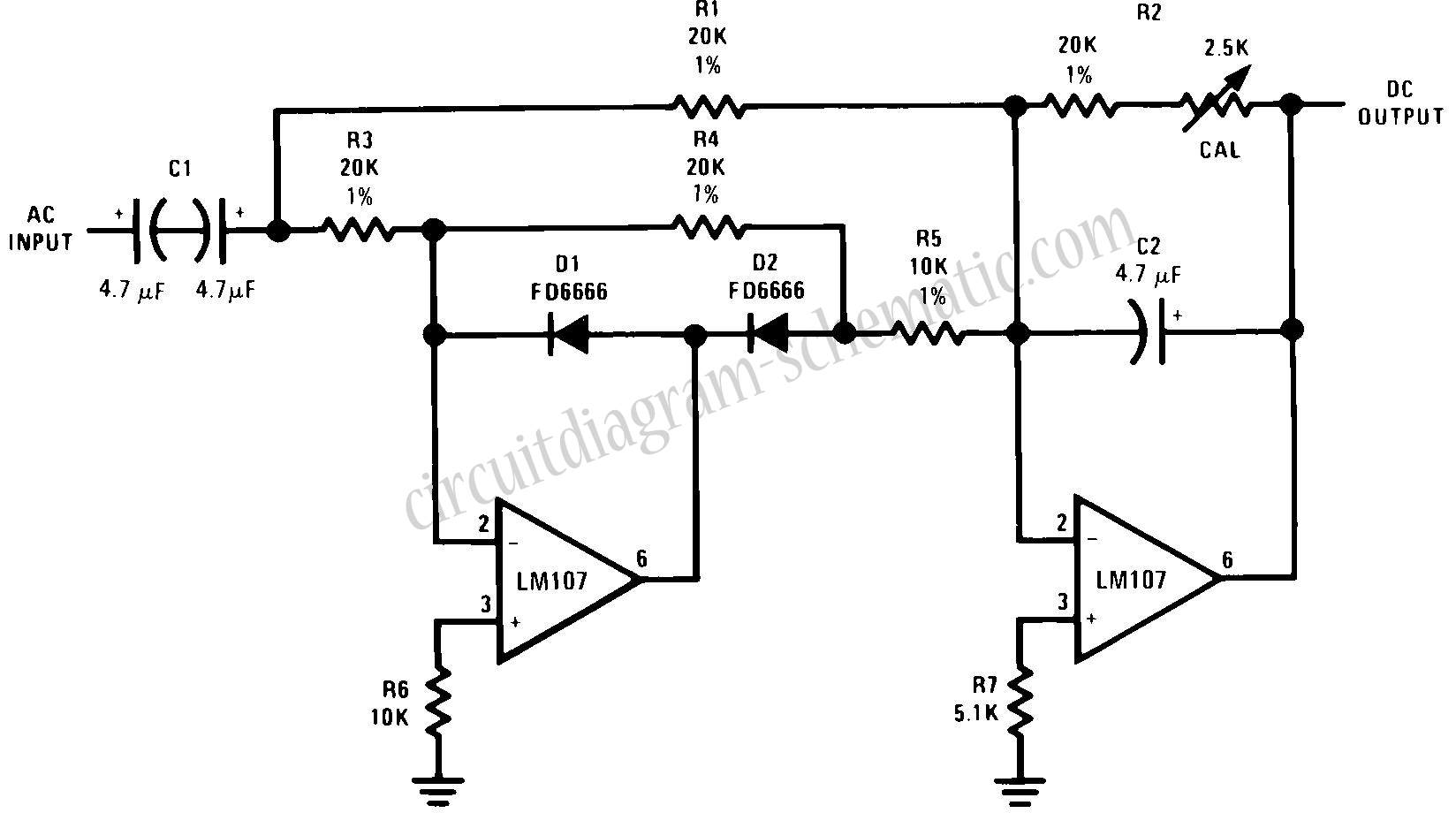
This circuit is an RMS-calibrated AC voltmeter that provides average readings. Removing capacitor C2 eliminates the averaging function, resulting in a precision full-wave rectifier, while removing capacitor C1 transforms the circuit into an absolute value generator. The operation of the...
SMOKE DETECTOR USING 555 TIMER
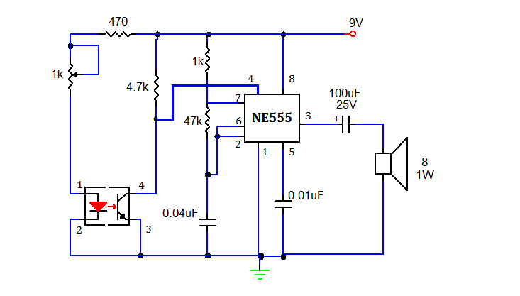
This document presents a simple smoke sensing alarm circuit utilizing a 555 timer. The circuit is designed to detect smoke and trigger an alarm when the air is contaminated. The components employed in this design include an astable multivibrator and...
simple temperature controller
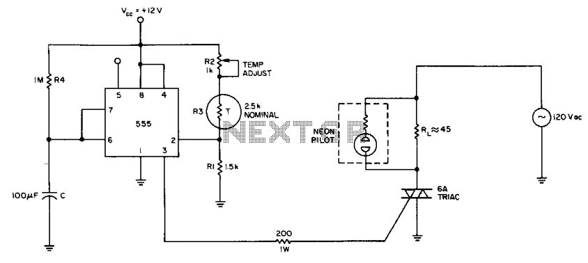
The internal comparator of the 555 timer, combined with a thermistor, creates a low-cost temperature controller. Resistor R2 establishes the temperature trip point.
The 555 timer is a versatile integrated circuit widely used in various applications, including timers, oscillators, and pulse...
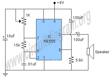
buzzer circuit
This project involves a 555 buzzer circuit utilizing the NE555 timer IC, which comes in an 8-pin DIP package and performs a wide variety of functions in electronic circuits. The circuit described will produce a buzzer sound when a 9-volt...
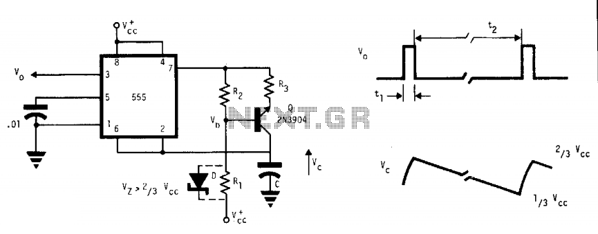
555 Astable oscillator
This free-running multivibrator utilizes an external current sink to discharge the timing capacitor, C. As a result, the interval can easily be 1000 times the pulse duration, t1, which defines a positive output. The voltage across the capacitor, V, exhibits...
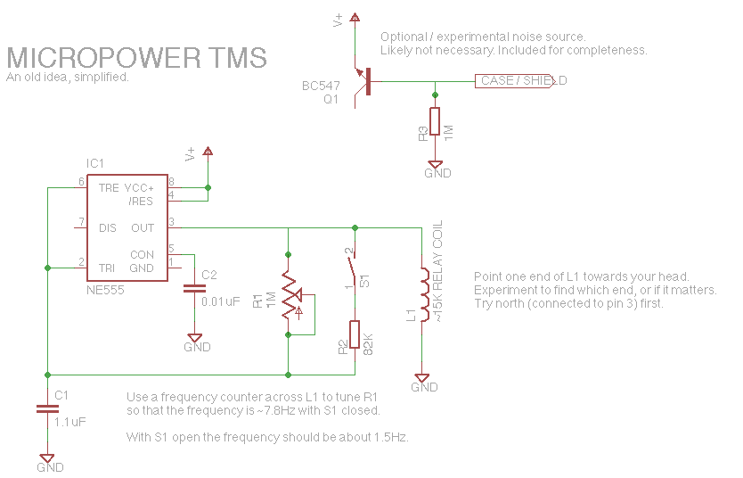
Tune Your Brainwaves Instantly with an Ultra-Simple 555 Circuit
Let's face it, not every day is the greatest. Sometimes, one may not feel like doing much of anything. Wouldn't it be nice if there was a way to change brain waves at the push of a button? Transcranial magnetic...
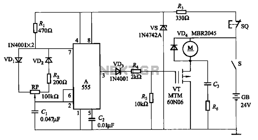
Variable speed electric motor bike circuit
The adjustment potentiometer (RP) allows for modification of the duty cycle of a square wave generated by the 555 integrated circuit (IC) in New Zealand, enabling control of motor speed within a range of 0 to 100%.
The circuit utilizes a...