


ACCURATE MOTOR SPEED CONTROL
#pyroelectric
#infrared
#voice alarm
#security
#automatic light switch
#electric shock prevention
#theft prevention
#integrated circuit
#human detection
Description: The SS0001 human pyroelectric voice alarm circuit diagram is designed for use as a pyroelectric infrared warning device, which can help prevent electric shock or theft. With minor modifications, it can also function as an automatic light switch. This circuit is based on integrated circuits, requiring only a few external components, making it easy to install and reliable, with minimal need for debugging. The infrared alarm switch utilizes a PIR (Passive Infrared) human pyroelectric sensor as a signal detector, featuring high sensitivity with a detection range exceeding 10 meters, a depression angle of up to 86 degrees, and a horizontal viewing angle of up to 120 degrees. The sensor detects specific wavelengths of infrared light emitted by the human body, resulting in minimal erroneous operation. When an individual is active within a frequency range of 0.3 to 3 Hz, the PIR sensor can generate a weak signal in the detection area, which is then amplified by operational amplifiers U1-1 and U1-2, transforming the output from U1 (pin 7) into a strong signal ranging from 0.5 to 5.5 volts.
The dual-threshold comparator, consisting of D4, D5, and resistors R12 to R15, processes the signal voltage induced by the PIR sensor, which can be either positive or negative. Consequently, the output voltage at U1 (pin 7) can also be positive or negative relative to a center voltage of 3V. When the output voltage exceeds 4.1V, D4 applies voltage to U1 (pin 10), surpassing the voltage at pin 9 (3.3V), resulting in a high output at U1 (pin 8). Conversely, if the output at U1 (pin 7) falls below 2V, the voltage at U1 (pin 9) drops to 2.7V or lower via D2, causing U1 (pin 8) to output a high signal. In the absence of a signal, U1 (pin 9) remains at 3.3V, while pin 10 is at 2.7V, leading to no output at pin 8. Upon detecting a PIR signal, a high output at pin 8 triggers a charge through D6 and resistor R17 to capacitor C9, elevating the voltage at U1 (pin 12) above pin 13, which in turn activates a bidirectional output thyristor to illuminate a lamp. The energy stored in capacitor C8 is discharged through R19 and RW2, keeping the light on for approximately two minutes. The light will turn off automatically once the voltage at C9 (pin 13) drops below 1V.
The circuit also incorporates a light control mechanism using a CDS photoresistor and a transistor (Q1). During daylight, the low resistance of the photoresistor (10K ohms or less) causes transistor Q1 to conduct fully, clamping U1 (pin 8) to approximately 0.3V. This ensures that regardless of the induction signal, the thyristor cannot turn on, preventing the lamp from lighting. At night, the higher resistance of the photoresistor, which can reach several megohms, turns off transistor Q1, allowing U1 (pin 8) to output a high signal upon receiving a PIR signal, thus activating the thyristor and lighting the lamp.
The LM324-based PIR switch circuit diagram illustrates the human pyroelectric infrared detection system, which primarily consists of a Fresnel lens, pyroelectric infrared sensors, and four operational amplifiers (LM324). When a human body enters the sensor's monitoring range, infrared energy is focused by the lens into the non-inverting input of the low-pass amplifier (IClA). Capacitors C1, C2, and C4 serve as high-frequency filter capacitors, while C3 and C5 manage the infrared channel's low-frequency AC signal. The inverting amplifier (ICIB) is configured using resistors R5 and R6, with a bias set to half the supply voltage at the non-inverting terminal, amplifying the AC signal. C7 acts as a high-frequency filter capacitor, while resistors R3, R2, R8, and R4 determine the overall amplification gain. The comparator (IClC) is set up to establish a reference voltage of approximately 3.9V through resistors R10 and R11, which simultaneously serves as a delay circuit for the monostable trigger in IClD. The output from IClB, influenced by the photosensitive resistor RG, is processed through resistor R9, with RG's resistance dropping to around 10k ohms during daylight, resulting in a high signal output from IClB through R9.Made of SS0001 human pyroelectric voice alarm circuit diagram as shown: Pyroelectric infrared language warning device described in this article can be used to prevent electric shock or theft, after a little modification can also be used for automatic light switches. Due to the integrated circuit-based, only a small number of external components, it is easy to install,
reliable, almost without debugging, as long as the assembly is correct, will be able to work properly. (View) Infrared alarm switch using the most popular PIR human pyroelectric sensor for signal detector, high sensitivity, detection range up to 10 meters above its depression angles up to 86 °, horizontal viewing angle up to 120 °.
It is only due to the release of the body, the specific wavelengths of infrared light sensitive, and thus erroneous operation minimal. When someone with 0. 3 ~ 3Hz frequency activity, PIR sensor can be induced in weak signal in the detection area by U1-1, U1-2 levels amplified from U1 (7) output of 0.
5 to 5. 5 feet V strong signal. D4, D5, R12 ~ R15 and U1-3 consisting of dual-threshold comparator, because the signal voltage induced PIR can be positive or negative, so U1 (7) pin output voltage can be positive or negative (in terms of the center voltage of 3V ). When the output voltage reaches 4. 1V or more, through D4 applied to U1 (10) pin voltage is higher than (9) pin voltage (3. 3V), so U1 (8) pin output high potential; And when U1 (7 ) when the pin output is below potential 2V, then U1 (voltage 9) pin will drop to 2.
7V or less through D2, U1 (8) feet high potential output. Usually when there is no signal, because U1 (9) feet above the potential 3. 3V (10) feet (2. 7V), so (8) feet no output. When the PIR signal is received (8) feet on certain high potential output through D6, R17 to C9 charge, so U1 (12) feet higher than the potential (13) feet, which (14) feet high potential trigger bidirectional output thyristor conduction, lit the lamp. The stored energy due C8 through R19, RW2 discharge takes about two minutes, so within this 2 minutes light stays lit.
When the voltage is lower than C9 (13) pin voltage (1V), the (14) feet no output, SCR turn off lights automatically turn off. CDS photoresistor composition and light control circuit transistor Q1, etc. , during the day due to a small photosensitive resistor (10K © or less), the transistor Q1 saturated conduction, the U1 (8) feet clamped to about 0.
3V, so regardless of whether the induction signal, SCR can not be turned on, the lamp can not be lit; night, due to larger photosensitive resistor to a few megohms, the transistor Q1 is turned off, U1 (8) feet no longer subject to the clamp, once receiving PIR signal, (8) feet immediately output high, the thyristor, the lamp is lit. (View) LM324 manufactured using low-cost PIR switch circuit diagram shown in Fig. : Human pyroelectric infrared detection portion, mainly by the Fresnel lens and pyroelectric infrared sensors, four operational amplifier (LM324) and other components.
When the range of the human body into the sensor monitoring, infrared energy lens focused into the low- pass amplifier noninverting IClA, C1, C2, C4 is a high frequency filter capacitor, C3, and C5 infrared channel low-frequency AC signal. ICIB for the inverting amplifier by R5, R6 and the partial pressure of the noninverting terminal of the bias IClB 1 / 2 Supply voltage to amplify the AC signal, C7 is a high frequency filter capacitor, the two amplifier R3, R2, R8, R4 determine the amplification gain.
IClC composition comparator, ‘© feet, through R10, R11 divider setting a reference voltage of about 3. 9V, the reference voltage is also at the same time as the delay circuit IClD monostable trigger threshold level, 1CIC the comparison voltage signal ‘¨ pin, in the photosensitive resistor RG acquired by IClB output through R9, daytime RG by light, resistance ‰¤ 10k ©, IClB high signal output by R9
The dual-threshold comparator, consisting of D4, D5, and resistors R12 to R15, processes the signal voltage induced by the PIR sensor, which can be either positive or negative. Consequently, the output voltage at U1 (pin 7) can also be positive or negative relative to a center voltage of 3V. When the output voltage exceeds 4.1V, D4 applies voltage to U1 (pin 10), surpassing the voltage at pin 9 (3.3V), resulting in a high output at U1 (pin 8). Conversely, if the output at U1 (pin 7) falls below 2V, the voltage at U1 (pin 9) drops to 2.7V or lower via D2, causing U1 (pin 8) to output a high signal. In the absence of a signal, U1 (pin 9) remains at 3.3V, while pin 10 is at 2.7V, leading to no output at pin 8. Upon detecting a PIR signal, a high output at pin 8 triggers a charge through D6 and resistor R17 to capacitor C9, elevating the voltage at U1 (pin 12) above pin 13, which in turn activates a bidirectional output thyristor to illuminate a lamp. The energy stored in capacitor C8 is discharged through R19 and RW2, keeping the light on for approximately two minutes. The light will turn off automatically once the voltage at C9 (pin 13) drops below 1V.
The circuit also incorporates a light control mechanism using a CDS photoresistor and a transistor (Q1). During daylight, the low resistance of the photoresistor (10K ohms or less) causes transistor Q1 to conduct fully, clamping U1 (pin 8) to approximately 0.3V. This ensures that regardless of the induction signal, the thyristor cannot turn on, preventing the lamp from lighting. At night, the higher resistance of the photoresistor, which can reach several megohms, turns off transistor Q1, allowing U1 (pin 8) to output a high signal upon receiving a PIR signal, thus activating the thyristor and lighting the lamp.
The LM324-based PIR switch circuit diagram illustrates the human pyroelectric infrared detection system, which primarily consists of a Fresnel lens, pyroelectric infrared sensors, and four operational amplifiers (LM324). When a human body enters the sensor's monitoring range, infrared energy is focused by the lens into the non-inverting input of the low-pass amplifier (IClA). Capacitors C1, C2, and C4 serve as high-frequency filter capacitors, while C3 and C5 manage the infrared channel's low-frequency AC signal. The inverting amplifier (ICIB) is configured using resistors R5 and R6, with a bias set to half the supply voltage at the non-inverting terminal, amplifying the AC signal. C7 acts as a high-frequency filter capacitor, while resistors R3, R2, R8, and R4 determine the overall amplification gain. The comparator (IClC) is set up to establish a reference voltage of approximately 3.9V through resistors R10 and R11, which simultaneously serves as a delay circuit for the monostable trigger in IClD. The output from IClB, influenced by the photosensitive resistor RG, is processed through resistor R9, with RG's resistance dropping to around 10k ohms during daylight, resulting in a high signal output from IClB through R9.Made of SS0001 human pyroelectric voice alarm circuit diagram as shown: Pyroelectric infrared language warning device described in this article can be used to prevent electric shock or theft, after a little modification can also be used for automatic light switches. Due to the integrated circuit-based, only a small number of external components, it is easy to install,
reliable, almost without debugging, as long as the assembly is correct, will be able to work properly. (View) Infrared alarm switch using the most popular PIR human pyroelectric sensor for signal detector, high sensitivity, detection range up to 10 meters above its depression angles up to 86 °, horizontal viewing angle up to 120 °.
It is only due to the release of the body, the specific wavelengths of infrared light sensitive, and thus erroneous operation minimal. When someone with 0. 3 ~ 3Hz frequency activity, PIR sensor can be induced in weak signal in the detection area by U1-1, U1-2 levels amplified from U1 (7) output of 0.
5 to 5. 5 feet V strong signal. D4, D5, R12 ~ R15 and U1-3 consisting of dual-threshold comparator, because the signal voltage induced PIR can be positive or negative, so U1 (7) pin output voltage can be positive or negative (in terms of the center voltage of 3V ). When the output voltage reaches 4. 1V or more, through D4 applied to U1 (10) pin voltage is higher than (9) pin voltage (3. 3V), so U1 (8) pin output high potential; And when U1 (7 ) when the pin output is below potential 2V, then U1 (voltage 9) pin will drop to 2.
7V or less through D2, U1 (8) feet high potential output. Usually when there is no signal, because U1 (9) feet above the potential 3. 3V (10) feet (2. 7V), so (8) feet no output. When the PIR signal is received (8) feet on certain high potential output through D6, R17 to C9 charge, so U1 (12) feet higher than the potential (13) feet, which (14) feet high potential trigger bidirectional output thyristor conduction, lit the lamp. The stored energy due C8 through R19, RW2 discharge takes about two minutes, so within this 2 minutes light stays lit.
When the voltage is lower than C9 (13) pin voltage (1V), the (14) feet no output, SCR turn off lights automatically turn off. CDS photoresistor composition and light control circuit transistor Q1, etc. , during the day due to a small photosensitive resistor (10K © or less), the transistor Q1 saturated conduction, the U1 (8) feet clamped to about 0.
3V, so regardless of whether the induction signal, SCR can not be turned on, the lamp can not be lit; night, due to larger photosensitive resistor to a few megohms, the transistor Q1 is turned off, U1 (8) feet no longer subject to the clamp, once receiving PIR signal, (8) feet immediately output high, the thyristor, the lamp is lit. (View) LM324 manufactured using low-cost PIR switch circuit diagram shown in Fig. : Human pyroelectric infrared detection portion, mainly by the Fresnel lens and pyroelectric infrared sensors, four operational amplifier (LM324) and other components.
When the range of the human body into the sensor monitoring, infrared energy lens focused into the low- pass amplifier noninverting IClA, C1, C2, C4 is a high frequency filter capacitor, C3, and C5 infrared channel low-frequency AC signal. ICIB for the inverting amplifier by R5, R6 and the partial pressure of the noninverting terminal of the bias IClB 1 / 2 Supply voltage to amplify the AC signal, C7 is a high frequency filter capacitor, the two amplifier R3, R2, R8, R4 determine the amplification gain.
IClC composition comparator, ‘© feet, through R10, R11 divider setting a reference voltage of about 3. 9V, the reference voltage is also at the same time as the delay circuit IClD monostable trigger threshold level, 1CIC the comparison voltage signal ‘¨ pin, in the photosensitive resistor RG acquired by IClB output through R9, daytime RG by light, resistance ‰¤ 10k ©, IClB high signal output by R9
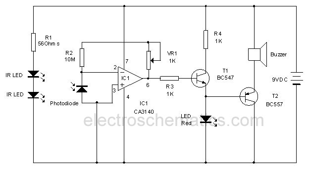
Invisible Infrared Alarm Circuit
This circuit utilizes invisible infrared light to detect the movement of individuals through a doorway. A brief beep will be emitted when the infrared beam is interrupted.
The infrared movement detection circuit employs an infrared LED and a photodiode or phototransistor...
Infrared Fire-Cracker Igniter
Firecrackers are typically ignited using a matchstick or a candle. It is important to move away quickly after lighting the fuse of the firecracker. This method..
Firecrackers operate on the principle of rapid combustion, which produces a loud noise and often...
nikon d50d70 ir remote control
Nikon infrared remote control with special features for interval shots, multiple shots, and continuous shots.
The Nikon infrared remote control is designed to enhance the photography experience by allowing users to capture images without physically touching the camera. This remote control...
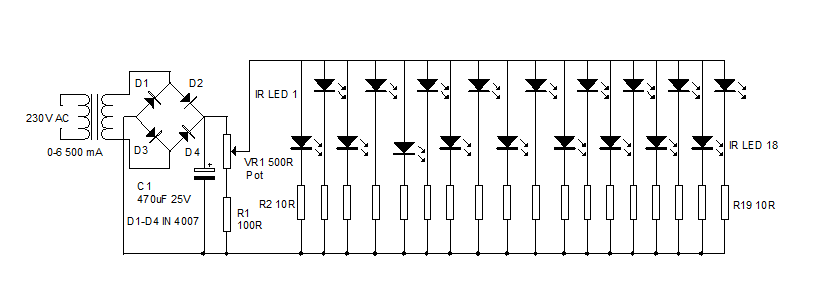
Simple Infrared Illuminator
An infrared illuminator emits light in the infrared spectrum and is widely used in night vision cameras to capture images in the dark, particularly in applications such as CCTV cameras.
Infrared illuminators are essential components in various surveillance and imaging systems,...
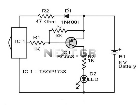
Remote Control Tester Circuit using Infra red sensor IC TSOP 1738
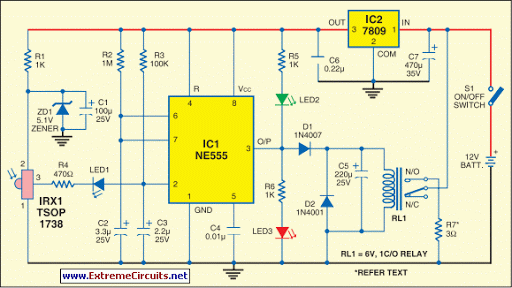
A simple remote control tester circuit with a diagram and schematic using the infrared sensor IC TSOP1738. An LED will blink when infrared waves fall on it, indicating the remote control is functioning.
The remote control tester circuit utilizes the TSOP1738...
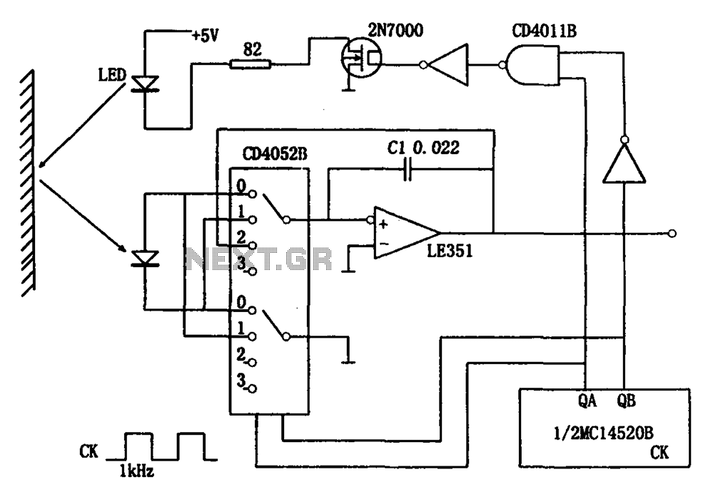
Reflected light intensity detecting circuit CD4052B CD4011B
The circuit for detecting the intensity of reflected light includes infrared light-emitting diodes, photodiodes, CMOS analog switches, operational amplifiers, and other components. When the circuit operates, the infrared light-emitting diode (LED) initially remains off, allowing the photodiode to receive external...

Design your Circuit IR Transmitter
Most consumer electronic devices utilize infrared remote controls for convenient operation. The carrier frequency of these remote controls typically ranges from 36 kHz to 38 kHz. Control codes are transmitted to the device's receiver in a serial format, which is...
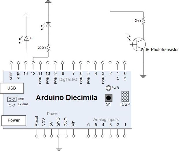
reading electricity meter ir impulses
Yesterday, an attempt was made to read the infrared impulses from an electricity meter using a phototransistor. The phototransistor can detect infrared signals from various remote controls in the house but fails to detect the blinking signal from the electricity...
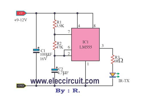
Infrared Remote control transmitters
This infrared remote control transmitter circuit exhibits high performance and can be utilized with various infrared receiver circuits. It is designed for ease of construction and cost-effectiveness. Additionally, another circuit is intended for broader applications and requires programming to emit...