


Adjustable threshold temperature alarm
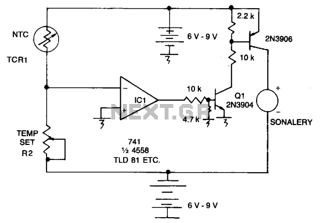
Description: As the resistance (Rl) increases with a decrease in temperature, the output of integrated circuit IC1 becomes positive, activating transistor Q1. When Q1 conducts, it also triggers transistor Q2, which in turn activates the audible alarm. The threshold level for this operation is adjusted using potentiometer R2.
The circuit described operates as a temperature-sensitive alarm system. In this configuration, the resistance Rl is inversely related to temperature, meaning that as the temperature drops, Rl increases. This increase in resistance affects the voltage level at the output of IC1, which is likely a comparator or operational amplifier configured to monitor the voltage across Rl.
When the output of IC1 goes positive, it indicates that the measured temperature has dropped below a predetermined threshold. This output is used to turn on transistor Q1, which acts as a switch in this circuit. The conduction of Q1 allows current to flow to transistor Q2, which is connected to the audible alarm. Thus, when Q2 is activated, it completes the circuit for the alarm, resulting in an audible signal indicating a low-temperature condition.
The threshold for triggering this alarm is adjustable through potentiometer R2. By varying the resistance of R2, the reference voltage at the input of IC1 can be altered, allowing for customization of the temperature level at which the alarm will activate. This feature is essential for applications requiring specific temperature monitoring, such as in refrigeration systems or environmental controls.
Overall, this circuit provides a simple yet effective means of monitoring temperature changes and alerting users when conditions fall outside of a desired range. The use of transistors for switching and an adjustable potentiometer for threshold setting enhances the flexibility and functionality of the design.When Rl increases as temp decreases, the output of IC1 goes positive, turning on Ql. Ql conducts and causes Q2 to conduct, turning on the audible alarm. The threshold is set with potentiometer R2.
The circuit described operates as a temperature-sensitive alarm system. In this configuration, the resistance Rl is inversely related to temperature, meaning that as the temperature drops, Rl increases. This increase in resistance affects the voltage level at the output of IC1, which is likely a comparator or operational amplifier configured to monitor the voltage across Rl.
When the output of IC1 goes positive, it indicates that the measured temperature has dropped below a predetermined threshold. This output is used to turn on transistor Q1, which acts as a switch in this circuit. The conduction of Q1 allows current to flow to transistor Q2, which is connected to the audible alarm. Thus, when Q2 is activated, it completes the circuit for the alarm, resulting in an audible signal indicating a low-temperature condition.
The threshold for triggering this alarm is adjustable through potentiometer R2. By varying the resistance of R2, the reference voltage at the input of IC1 can be altered, allowing for customization of the temperature level at which the alarm will activate. This feature is essential for applications requiring specific temperature monitoring, such as in refrigeration systems or environmental controls.
Overall, this circuit provides a simple yet effective means of monitoring temperature changes and alerting users when conditions fall outside of a desired range. The use of transistors for switching and an adjustable potentiometer for threshold setting enhances the flexibility and functionality of the design.When Rl increases as temp decreases, the output of IC1 goes positive, turning on Ql. Ql conducts and causes Q2 to conduct, turning on the audible alarm. The threshold is set with potentiometer R2.
General-Purpose Alarm
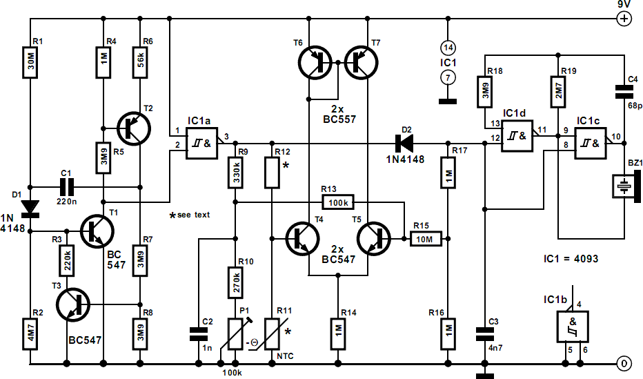
The alarm can be utilized for various applications, including frost monitoring and room temperature monitoring. In its quiescent state, the circuit consumes only a few microamperes, allowing a 9 V dry battery (PP3, 6AM6, MN1604, 6LR61) to potentially last up...

Transistorized Bar-Graph Driver
A resistor network (R1 through R10) with emitter followers (Q1 and Q2) drives LED drivers (Q3 through Q7). This circuit was utilized as a "light organ" to provide visual volume indication. It can be connected to a speaker, another audio...

PC thermometer schematic
This incredibly simple thermometer plugs on any free serial port. Does not make use of any programmable components as microcontrollers. It gives temperature readings accurate to 0.5°C with no calibration. It's cheap, so I've put one on any PC I...
Common emitter amplifier works a
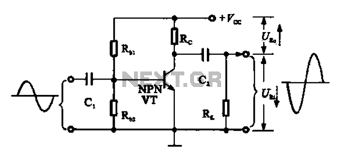
A common emitter amplifier functions as a signal amplification unit by utilizing a common emitter configuration, which inverts the output signal. This operation can be analyzed by observing the input signal waveform. During the first quarter of the period, the...

Dual adjustable power supply circuit
The circuit utilizes a three-terminal adjustable integrated voltage regulator. It includes a gear set and a power supply voltage that is stepped down using a transformer rated at 17.5V x 2 AC. The output voltage after the bridge rectifier is...
Simple Audio amplifier Using Transistors
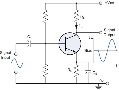
Construct a basic audio amplifier utilizing transistors. While integrated circuit (IC) designs are available for this purpose, the intention is to use transistors to gain practical knowledge about their amplification capabilities. The article "Amplifier Basics - How Amps Work (Intro)"...
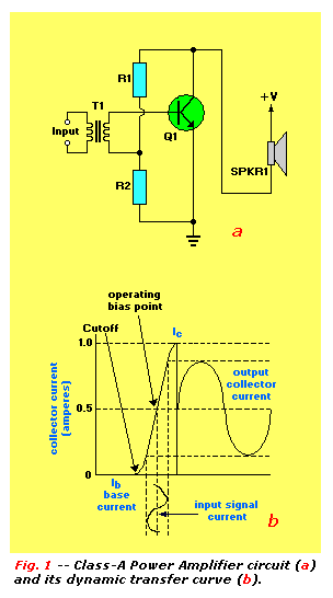
Transistor Tutorial Power Amplifiers Part 4
An audio power amplifier can enhance weak signals from devices like tuners, CD players, or tape decks to fill a room with sound. This article emphasizes the operating principles and circuitry of low-frequency power amplifiers utilizing bipolar junction transistors (BJTs)....
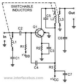
Transistor Circuits
This page presents several transistor circuits that are not commonly found on other pages due to the absence of a specific topic. These circuits, however, illustrate particular points but lack detailed descriptions. An example of an RF amplifier circuit using...
Differential-thermometer
The differential thermometer utilizes two probes to display the temperature difference between them instead of indicating the precise temperature. It employs a conventional meter as an indicator and has a total range of -10°C to 20°C.
The differential thermometer operates on...