


Alarm Phone Dialer
#phone dialer
#alarm system
#monitoring
#security
#automated call
#alert system
#home security
#programmable
#remote monitoring
#sensor trigger
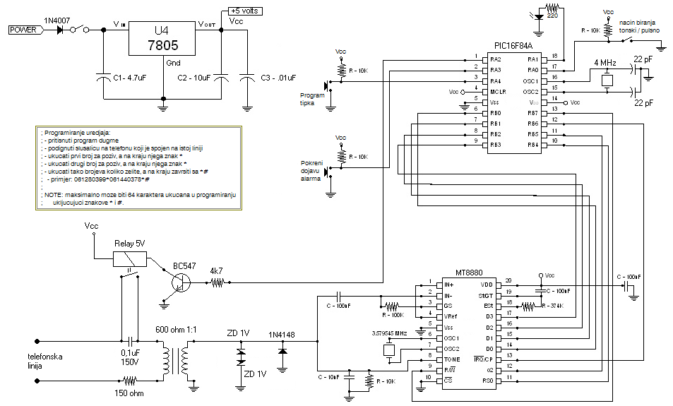
Description: Connect this Alarm Phone Dialer to a device you wish to monitor, such as a high water alarm, low temperature alarm, back window, or garage door. When activated, it will call a series of pre-programmed numbers to notify you of the alarm condition, making it ideal for receiving alerts while away from home. The accompanying microcontroller code is available on the website. The circuit utilizes an MT8880 DTMF dialer chip and a PIC 16F84A microcontroller. For those who prefer not to build their own dialer, professional monitoring services are available for various security needs. After assembling the device, enter programming mode to input phone numbers that the module will dial upon detecting an input on its sensor pin. Once programmed, power the device and press the "Start Alarm Notification" button to initiate dialing (tone or pulse mode can be selected with a jumper). When the call is successfully connected, the recipient must press the pound key (#) to prevent the device from dialing additional numbers. Instead of the "Start Alarm Notification" button, a sensor should be connected. To program numbers: 1. Press the "Program" button. 2. Use a phone on the same line as the device. 3. Enter the first number followed by the star (*) key. 4. Enter the next number followed by the star (*) key. 5. Continue entering numbers, concluding with the sequence followed by the star and hash (*#) keys (e.g., 061123123*061456456*#). Note that the device can learn up to 64 characters/digits, including the star and hash keys.
The Alarm Phone Dialer is designed to provide a reliable notification system for various monitoring applications. The integration of the MT8880 DTMF dialer chip allows for efficient telephone dialing using Dual-Tone Multi-Frequency signaling, which is essential for communicating with standard telephone networks. The PIC 16F84A microcontroller serves as the central processing unit, managing the logic required for both the detection of alarm conditions and the dialing process.
The device operates by monitoring a designated sensor input, which can be connected to various types of sensors depending on the application. For instance, a float switch could be used for water level monitoring, while a temperature sensor could be employed for temperature thresholds. Upon detecting an alarm condition, the microcontroller activates the dialing sequence, utilizing the programmed phone numbers stored in its memory.
Programming the device involves a straightforward sequence that allows the user to input multiple phone numbers. This flexibility ensures that notifications can be sent to different contacts, enhancing the reliability of the alert system. The use of the pound key (#) as a confirmation signal to stop further dialing is a practical feature, preventing unnecessary calls once the alert has been acknowledged.
The device's design also accommodates user customization, allowing individuals to modify the jumper settings for dialing modes. This adaptability ensures compatibility with various telephone systems and user preferences. The ability to learn up to 64 digits, including special characters, provides ample space for programming multiple contacts.
Overall, the Alarm Phone Dialer represents a practical solution for remote monitoring and alerting, combining ease of use with robust functionality. Its straightforward assembly and programming process make it accessible for both hobbyists and those seeking to implement a basic security system without professional assistance.Just hook this Alarm Phone Dialer up to something you would like to monitor, for example, a high water alarm, low temperature alarm, back window, garage door, etc. When the system is activated it will call a number of programmed numbers to let you know the alarm has been activated.
This would be great to get alerts of alarm conditions from your ho me when you are at work. The microcontroller code is provided on the site. The circuit uses a MT8880 DTMF dialer chip and a PIC 16F84A microcontroller. If you don`t feel up to the challenge of building your own dialer you can always look to the professionals to monitor anything you like with a modern security system. After putting together this little device, you must enter programming-mode to learn some phone numbers which this module will call after detecting an input on it`s sensor pin.
After programming just supply power to the device. After pressing the button Pokreni dojavu alarma it will start to dial (tone or pulse, depending on the jumper setup). When the phone call is successfully established, the called party should press pound key # to stop the device from calling another number or again.
You should put a sensor instead of button Pokreni dojavu alarma . Programming the numbers 1. press the program button 2. pick up the phone that is connected to the same phone-line as this device 3. punch-in first number and then * key 4. punch-in then next number and then * key 5. punch-in the rest of numbers, if more, and finalise with *# (example: 061123123*061456456*#) Please note: The device will learn 64 characters/digits including * and # keys.
The Alarm Phone Dialer is designed to provide a reliable notification system for various monitoring applications. The integration of the MT8880 DTMF dialer chip allows for efficient telephone dialing using Dual-Tone Multi-Frequency signaling, which is essential for communicating with standard telephone networks. The PIC 16F84A microcontroller serves as the central processing unit, managing the logic required for both the detection of alarm conditions and the dialing process.
The device operates by monitoring a designated sensor input, which can be connected to various types of sensors depending on the application. For instance, a float switch could be used for water level monitoring, while a temperature sensor could be employed for temperature thresholds. Upon detecting an alarm condition, the microcontroller activates the dialing sequence, utilizing the programmed phone numbers stored in its memory.
Programming the device involves a straightforward sequence that allows the user to input multiple phone numbers. This flexibility ensures that notifications can be sent to different contacts, enhancing the reliability of the alert system. The use of the pound key (#) as a confirmation signal to stop further dialing is a practical feature, preventing unnecessary calls once the alert has been acknowledged.
The device's design also accommodates user customization, allowing individuals to modify the jumper settings for dialing modes. This adaptability ensures compatibility with various telephone systems and user preferences. The ability to learn up to 64 digits, including special characters, provides ample space for programming multiple contacts.
Overall, the Alarm Phone Dialer represents a practical solution for remote monitoring and alerting, combining ease of use with robust functionality. Its straightforward assembly and programming process make it accessible for both hobbyists and those seeking to implement a basic security system without professional assistance.Just hook this Alarm Phone Dialer up to something you would like to monitor, for example, a high water alarm, low temperature alarm, back window, garage door, etc. When the system is activated it will call a number of programmed numbers to let you know the alarm has been activated.
This would be great to get alerts of alarm conditions from your ho me when you are at work. The microcontroller code is provided on the site. The circuit uses a MT8880 DTMF dialer chip and a PIC 16F84A microcontroller. If you don`t feel up to the challenge of building your own dialer you can always look to the professionals to monitor anything you like with a modern security system. After putting together this little device, you must enter programming-mode to learn some phone numbers which this module will call after detecting an input on it`s sensor pin.
After programming just supply power to the device. After pressing the button Pokreni dojavu alarma it will start to dial (tone or pulse, depending on the jumper setup). When the phone call is successfully established, the called party should press pound key # to stop the device from calling another number or again.
You should put a sensor instead of button Pokreni dojavu alarma . Programming the numbers 1. press the program button 2. pick up the phone that is connected to the same phone-line as this device 3. punch-in first number and then * key 4. punch-in then next number and then * key 5. punch-in the rest of numbers, if more, and finalise with *# (example: 061123123*061456456*#) Please note: The device will learn 64 characters/digits including * and # keys.
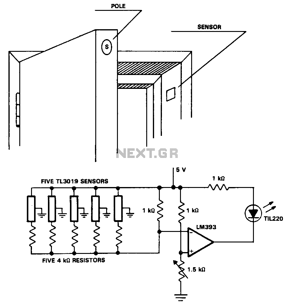
Security-door-ajar-alarm
The TL3019 device activates, or goes low, when a south pole of a magnet approaches the chip face. In this example, there are five doors, each equipped with a magnet embedded in its edge, with the south pole facing outward....
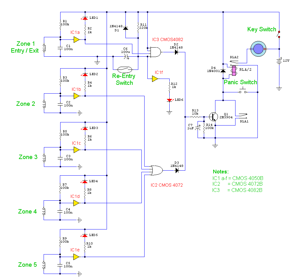
5 Zone Alarm System
This is a complete alarm system with five independent zones suitable for a small office or home environment. It utilizes three CMOS integrated circuits and features a timed entry/exit zone, four immediate zones, and a panic button. There are indicators...
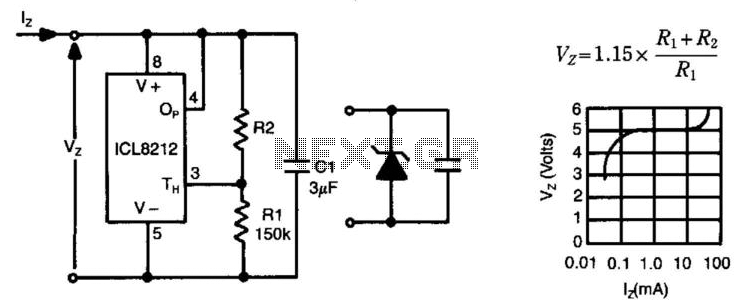
Programmable Zener
The ICL8212 is configured as a programmable zener diode, allowing for the programming of zener voltages ranging from 2 V to 30 V by appropriately selecting R2. The zener voltage is influenced by this selection. Additionally, due to the lack...
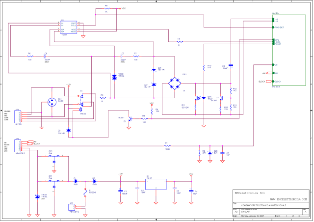
TT Phone Dialer
SINCLAIR is a one-channel phone dialer capable of transmitting alarm messages, which have been previously recorded to non-volatile DAST memory, over the commuted phone line to designated numbers stored in non-volatile EEPROM memory.
The SINCLAIR phone dialer operates by utilizing a...
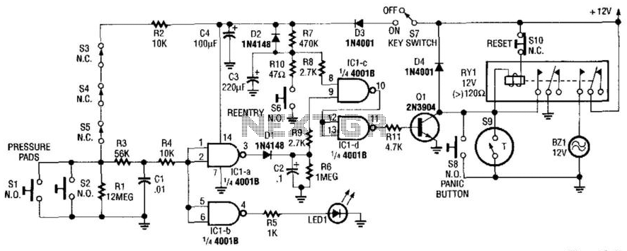
Home Security System
This alarm circuit activates when switches S1 through S5 are engaged. This action illuminates LED1 and triggers transistor Q1 through integrated circuits IC1C and IC1D. Relay RY1 is configured for self-latching. Switch S10 is utilized for resetting the circuit. When...
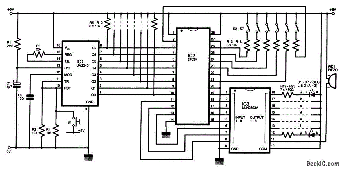
PROGRAMMABLE_TIMER_SEQUENCER
The circuit diagram of this programmable sequencer can be utilized for various timing applications. An audible tone is generated before the start of each interval, while a seven-segment LED display indicates the current interval number. A buzzer sounds again just...
PROGRAMMABLE_TIMER_SEQUENCER
The circuit diagram of this programmable sequencer can be utilized for various timing applications. An audible tone is generated before the start of each interval, while a seven-segment LED display indicates the current interval number. A buzzer sounds again just...
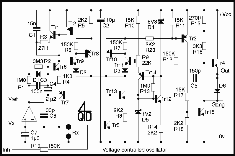
Programmable Clock Oscillator
This is a voltage controller oscillator that was designed as a wide range oscillator to generate clock pulses for a stepper motor drive system. It does however have some interesting features. The original application used a stepper motor for its...

6 Zone Alarm with LED Display Circuit With LM7805 IC
This circuit consists of a 6 Zone Alarm system with an LED display. The alarm system features 6 independent zones and includes a 7-segment LED display, along with one timed entry/exit zone.
The 6 Zone Alarm system is designed to provide...