


Allarm antifurto
#Nutchip
#radio receiver
#antenna
#remote control
#sensor
#decoder
#home security
#wireless
#signal decoding
#DIY

Description: The Nutchip decodes signals, distinguishing between immediate and delayed sensors, in addition to true remote control signals used for switching the circuit on and off. It is important to note that a good radio receiver cannot substitute for a good antenna. The circuit functions effectively with a homemade antenna (straight insulated wire), should budget constraints prevent the use of a commercial one. In addition to wireless sensors, the schematic also accommodates inputs for wired sensors. These sensors are configured as normally closed contacts, which open when someone enters their range or when a door or window is opened. Often, these sensors include a secondary anti-tamper contact that opens if the case is accessed or tampered with. Consequently, two inputs are required: one for connecting anti-tamper and immediate contacts, and another for connecting delayed contacts. The "immediate" input is connected to the Nutchip pin IN1, while the "delayed" input connects to pin IN2. Given that the wires are typically long enough to pick up noise and interference, two identical networks provide effective signal cleaning and clipping before the input signal reaches the chip. These networks consist of R7-R9-C5-DZ2 and R6-R8-C4-DZ1, respectively. All outputs are linked to LED diodes (DL1, DL2, DL3, DL4) to indicate the status of the main board. A siren is connected to the fourth output through RELAY1. As this circuit is designed for continuous operation, brown-outs are a potential issue. A brown-out refers to a significant drop in mains voltage that does not result in a complete blackout. Brown-outs can be detrimental to electronic devices, potentially leading to improper or partial resets with unpredictable outcomes. To mitigate this risk, IC2, a specialized voltage detector and RESET generator, has been incorporated. Along with the delay network R10-C6, it ensures a proper reset of the circuit even under adverse conditions. The board requires a 12V DC power supply. It is standard practice to power an alarm system using a battery that is continuously recharged to maintain functionality during power outages. Most alarm sensors also require a 12V DC power supply. The battery must be sufficiently sized to power both the central unit and the sensors for an adequate duration. To create a stabilized 5V power source needed for the Nutchip, a conventional regulator based on the 7805 (IC3) is employed, as illustrated in the schematic. To activate the alarm system, the first pushbutton on the remote control (key1) must be pressed. LED DL1 will illuminate, indicating activation.
The Nutchip-based circuit serves as a versatile solution for integrating both wireless and wired sensor systems, enhancing security through immediate and delayed response mechanisms. The differentiation between sensor types allows for tailored responses to various security events, ensuring that immediate threats are addressed promptly while also accommodating delayed responses for less urgent situations. The integration of anti-tamper sensors adds an additional layer of security, further protecting the system from unauthorized access.
The signal conditioning networks (R7-R9-C5-DZ2 and R6-R8-C4-DZ1) are critical for maintaining signal integrity, particularly in environments where electromagnetic interference may be prevalent. These networks filter out unwanted noise and ensure that the signals reaching the Nutchip are clean and reliable, which is essential for the proper functioning of the entire system.
The LED indicators provide real-time feedback on the status of the system, allowing users to quickly ascertain whether the system is armed or disarmed. The inclusion of a siren connected through RELAY1 serves as an audible alert, further enhancing the system's deterrent capabilities.
The provision for a battery backup underscores the importance of maintaining operation during power failures, a common scenario in security applications. The use of a 12V DC power supply is standard in alarm systems, ensuring compatibility with most sensors and devices. The voltage detection and reset mechanism (IC2 and R10-C6) is a sophisticated feature that enhances the reliability of the circuit, protecting it from potential damage caused by brown-outs.
Overall, this circuit design exemplifies a robust approach to security system architecture, combining multiple sensor types, effective signal processing, and reliable power management to deliver a comprehensive security solution.The Nutchip decodes the signal, differentiating between immediate and delayed sensors (aside from true remote control signals used for switching the circuit on and off). As for all radio-based designs, always remember that a good radio receiver cannot replace a good antenna.
The circuit works well with an home made antenna (straight insulated wire), should your budget forbid a commercial one. Wireless sensors aside, our schematic provides also inputs for wired sensors. Such sensors are treated as normally closed contacts, that break when someone enters their range or opens a door or window. It is often the case that they provide a second anti-tamper contact, which breaks if you open the case or attempt a sabotage.
Therefore we need two inputs: one for connecting anti tamper and immediate contacts and another one for connecting the delayed contacts. The "immediate" input is connected to the Nutchip pin IN1, and the "delayed" on to pin IN2. As the wires are usually long enough to collect any sort of noise and interference, a couple of identical networks provide quite an energic cleanup and clipping on the input signal before it arrives to the chip.
These networks are built around R7-R9-C5-DZ2 and R6-R8-C4-DZ1 respectively. All of the output are connected to a LED diode (DL1, DL2, DL3, DL4), in order to display the status of the main board. A siren is connected to the fourth output, through RELAY1. As this circuit is designed for uninterrupted service, brown-outs are a possibility that cannot be excluded.
A brown-ut is a big decrease in the mains voltage level that does not end in a black out. Brown-outs are dangerous for electronics devices, because it can result in improper or partial reset with impredictable consequences. This is why whe have added IC2, a special voltage detector and RESET generator. Together with the delay network R10-C6, it ensures a graceful reset to the circuit even in worst cases.
The board requires a 12Vdc power supply. It is common practice to power an alarm from a battery (kept under constant recharging), in order to be immune from power shortages. Most alarm sensors require a 12Vdc power supply as well. The battery must be big enough to power the central AND the sensors for an appropriate period of time.
To create a stabilized 5 volt power source required by the Nutchip, we adopted a "classic" regulator, based on the 7805 (IC3), as shown in the schematic on the left. To engage the alarm system press the first pushbutto on the remote control (key1). LED DL1 will lights up: starting now, we have 3 m
The Nutchip-based circuit serves as a versatile solution for integrating both wireless and wired sensor systems, enhancing security through immediate and delayed response mechanisms. The differentiation between sensor types allows for tailored responses to various security events, ensuring that immediate threats are addressed promptly while also accommodating delayed responses for less urgent situations. The integration of anti-tamper sensors adds an additional layer of security, further protecting the system from unauthorized access.
The signal conditioning networks (R7-R9-C5-DZ2 and R6-R8-C4-DZ1) are critical for maintaining signal integrity, particularly in environments where electromagnetic interference may be prevalent. These networks filter out unwanted noise and ensure that the signals reaching the Nutchip are clean and reliable, which is essential for the proper functioning of the entire system.
The LED indicators provide real-time feedback on the status of the system, allowing users to quickly ascertain whether the system is armed or disarmed. The inclusion of a siren connected through RELAY1 serves as an audible alert, further enhancing the system's deterrent capabilities.
The provision for a battery backup underscores the importance of maintaining operation during power failures, a common scenario in security applications. The use of a 12V DC power supply is standard in alarm systems, ensuring compatibility with most sensors and devices. The voltage detection and reset mechanism (IC2 and R10-C6) is a sophisticated feature that enhances the reliability of the circuit, protecting it from potential damage caused by brown-outs.
Overall, this circuit design exemplifies a robust approach to security system architecture, combining multiple sensor types, effective signal processing, and reliable power management to deliver a comprehensive security solution.The Nutchip decodes the signal, differentiating between immediate and delayed sensors (aside from true remote control signals used for switching the circuit on and off). As for all radio-based designs, always remember that a good radio receiver cannot replace a good antenna.
The circuit works well with an home made antenna (straight insulated wire), should your budget forbid a commercial one. Wireless sensors aside, our schematic provides also inputs for wired sensors. Such sensors are treated as normally closed contacts, that break when someone enters their range or opens a door or window. It is often the case that they provide a second anti-tamper contact, which breaks if you open the case or attempt a sabotage.
Therefore we need two inputs: one for connecting anti tamper and immediate contacts and another one for connecting the delayed contacts. The "immediate" input is connected to the Nutchip pin IN1, and the "delayed" on to pin IN2. As the wires are usually long enough to collect any sort of noise and interference, a couple of identical networks provide quite an energic cleanup and clipping on the input signal before it arrives to the chip.
These networks are built around R7-R9-C5-DZ2 and R6-R8-C4-DZ1 respectively. All of the output are connected to a LED diode (DL1, DL2, DL3, DL4), in order to display the status of the main board. A siren is connected to the fourth output, through RELAY1. As this circuit is designed for uninterrupted service, brown-outs are a possibility that cannot be excluded.
A brown-ut is a big decrease in the mains voltage level that does not end in a black out. Brown-outs are dangerous for electronics devices, because it can result in improper or partial reset with impredictable consequences. This is why whe have added IC2, a special voltage detector and RESET generator. Together with the delay network R10-C6, it ensures a graceful reset to the circuit even in worst cases.
The board requires a 12Vdc power supply. It is common practice to power an alarm from a battery (kept under constant recharging), in order to be immune from power shortages. Most alarm sensors require a 12Vdc power supply as well. The battery must be big enough to power the central AND the sensors for an appropriate period of time.
To create a stabilized 5 volt power source required by the Nutchip, we adopted a "classic" regulator, based on the 7805 (IC3), as shown in the schematic on the left. To engage the alarm system press the first pushbutto on the remote control (key1). LED DL1 will lights up: starting now, we have 3 m
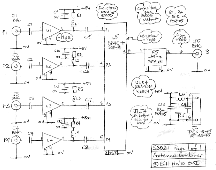
Antenna Combiner
The Antenna Combiner (A3021) is an active combiner designed to accommodate four 50-ohm coaxial antenna connections. It combines the signals from these four inputs, resulting in a net gain of approximately +11 dB. The A3021 is specifically intended for use...
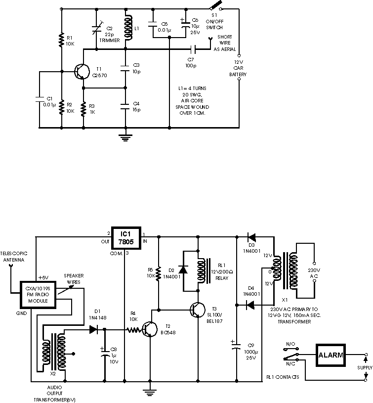
Car Wireless Alarm
This FM radio-controlled anti-theft system can be used with any device operating on a 6 to 12-volt DC power supply. The mini VHF FM transmitter is installed in the vehicle at night when it is parked in the driveway or...

Wireless am microphone
The transistor Q1 and its associated components form a tunable RF oscillator. The RF signal is directed to transistor Q2, which functions as the modulator. Operational amplifier IC1 amplifies the audio signal and transmits it through resistor R4 to the...

Wireless Microphone
Q1 amplifies the output from an electret microphone (MIC1). The audio signal is fed into oscillator Q2, which modulates the signal. Additionally, L1 and C1 form a tank circuit designed for operation in the 88-MHz frequency range. The antenna consists...
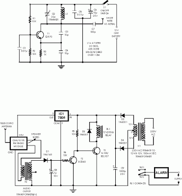
Schematic Diagram Anti Theft Car wireless alarm
This is an anti-theft alarm with wireless connectivity, referred to as the Anti-Theft Car Wireless Alarm. The FM radio-controlled anti-theft alarm can be utilized with any vehicle that operates on a 6 to 12-volt DC supply system. The mini VHF...
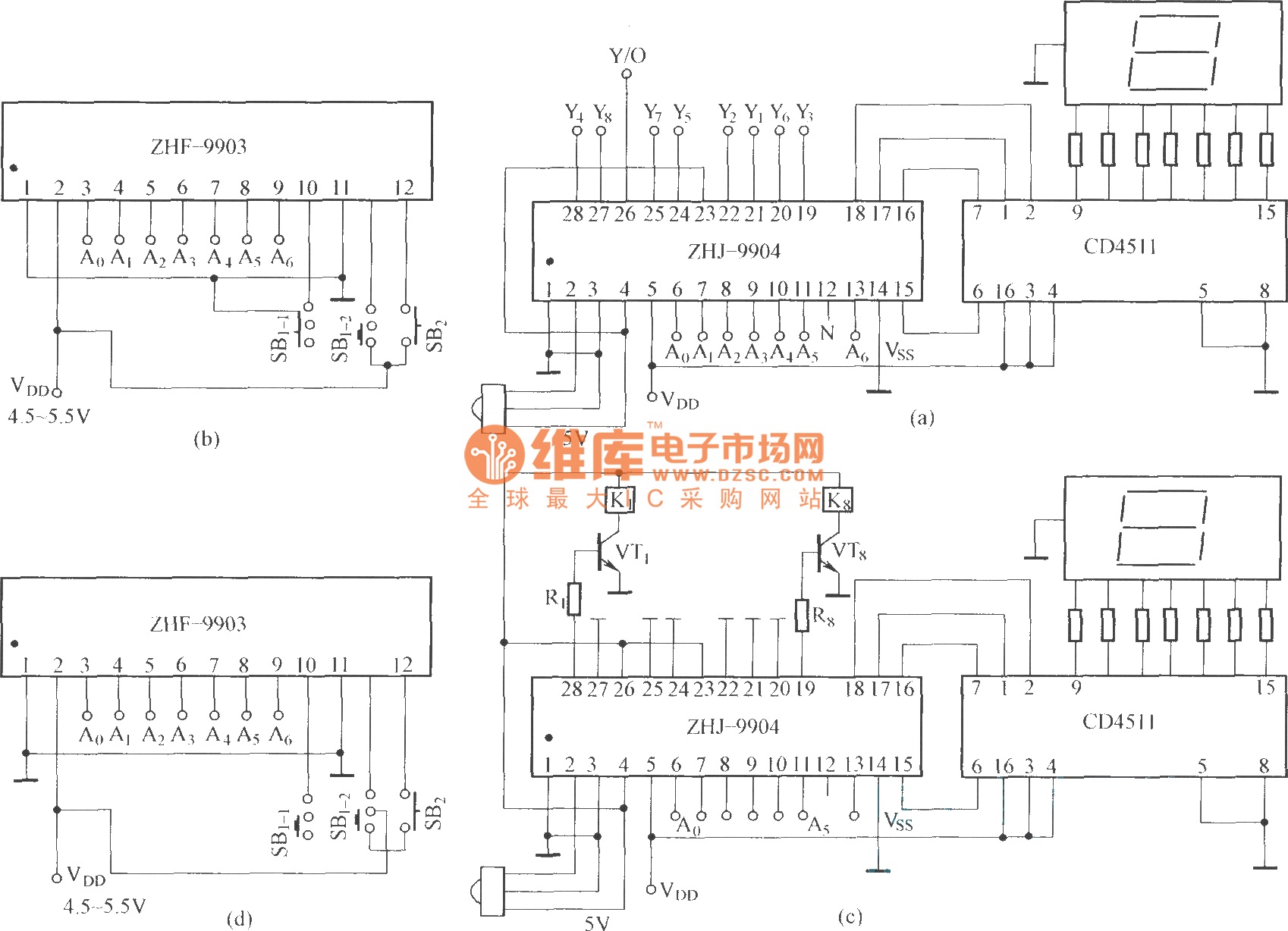
The eight-way remote control circuit diagram composed of module
This is an eight-way signal remote control selection circuit composed of ZHJ-9904. It includes a remote control transmitter circuit, an eight-way switch control circuit, and a remote control transmitter.
The eight-way signal remote control selection circuit utilizing the ZHJ-9904 is designed...
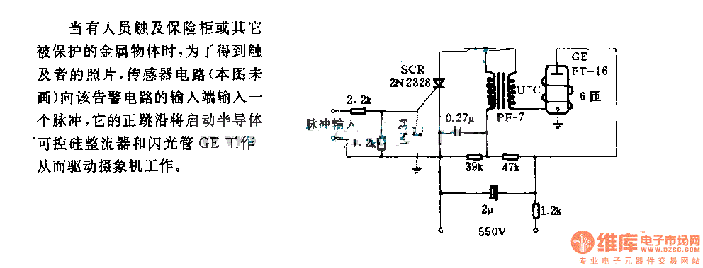
The alarm circuit diagram for safety box and other metal objects
When an individual touches the safety box or other protected metal objects, the sensor circuit generates a pulse to the alarm circuit. The positive edge of this pulse activates the semiconductor and thyristor flash GE, subsequently triggering the camera to...

Antenna tunning circuit for 27MHz CB band
The antenna tuning circuit can accommodate 1/2 wave length antennas or higher, for input resistances of 50 Ohms which make it suitable for CB (Citizen Band) transceivers. C1 is for fine tuning and C2 is just for tuning. Turning C3...
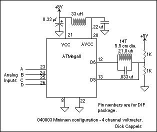
Wireless Coupled Scanning Voltmeter (ATMega8)
A 10 bit scanning voltmeter with a Minimum Mass Wireless Coupler, based on the ATMega8. Range to the Minimum Mass Base Unit is 10 to 15 cm. If the voltmeter is battery operated, it can be floated from ground. This...