


burglar alarm using ic timer 555556
#IC 555
#burglar alarm
#security
#timer circuit
#loud alarm
#thin wire trigger
#home security
#5-15V power supply
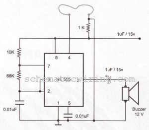
Description: The circuit of a burglar alarm utilizing IC timer 555/556 functions as a security measure to prevent unauthorized entry into a premises. The alarm generates a loud sound when a thin wire connecting resistor R1 with pin 4 of the IC is severed. A thin fiber is employed as the wire, with thinner wires yielding a more responsive alarm. This circuit requires a power supply of 5-15V, and a buzzer is used as the sound output device.
The burglar alarm circuit using the 555/556 timer IC operates in a monostable or astable mode, depending on the configuration. In this setup, the circuit is designed to monitor the integrity of a thin wire, which acts as a security sensor. When the wire is intact, the circuit remains in a low-power state. However, if the wire is cut or broken, the resulting change in resistance at the input pin of the timer IC triggers an output signal.
The circuit typically includes the following components:
1. **IC Timer 555/556**: This is the core component that generates the alarm signal. It can be configured in monostable mode to produce a single pulse or in astable mode for continuous oscillation.
2. **Resistor (R1)**: This resistor is connected to the thin wire and the IC. Its value is chosen to set the sensitivity of the circuit; a lower resistance increases sensitivity.
3. **Thin Wire (Sensor)**: The wire acts as a switch, completing the circuit when intact and breaking the circuit when cut.
4. **Buzzer**: The output device that produces sound when the alarm is triggered. The buzzer can be a piezoelectric or electromagnetic type, depending on the desired sound output.
5. **Power Supply**: The circuit requires a DC power supply ranging from 5V to 15V to operate the timer IC and the buzzer effectively.
The sensitivity of the alarm can be adjusted by changing the thickness of the wire or the resistor value. A thinner wire will break more easily, resulting in a quicker response time for the alarm system. For optimal performance, the circuit should be housed in a secure enclosure to prevent tampering, and the wire should be strategically placed to cover potential entry points.
In conclusion, this burglar alarm circuit is a simple yet effective solution for enhancing home security, utilizing basic electronic components to create an alert system that responds to unauthorized access attempts.circuit of burglar alarm using IC timer 555/556 is functioned as an alarm to prevent thief entering your house. The alarm would produce loud sound when a thin wire connecting resistor R1 with IC pin no 4 is broken.
Thin fiber is used as the wire. The thinner the wire, the more responsive the alarm. This circuit needs 5-15V power supply, bu zzer is used as a speaker. Here is the circuit schematic :
The burglar alarm circuit using the 555/556 timer IC operates in a monostable or astable mode, depending on the configuration. In this setup, the circuit is designed to monitor the integrity of a thin wire, which acts as a security sensor. When the wire is intact, the circuit remains in a low-power state. However, if the wire is cut or broken, the resulting change in resistance at the input pin of the timer IC triggers an output signal.
The circuit typically includes the following components:
1. **IC Timer 555/556**: This is the core component that generates the alarm signal. It can be configured in monostable mode to produce a single pulse or in astable mode for continuous oscillation.
2. **Resistor (R1)**: This resistor is connected to the thin wire and the IC. Its value is chosen to set the sensitivity of the circuit; a lower resistance increases sensitivity.
3. **Thin Wire (Sensor)**: The wire acts as a switch, completing the circuit when intact and breaking the circuit when cut.
4. **Buzzer**: The output device that produces sound when the alarm is triggered. The buzzer can be a piezoelectric or electromagnetic type, depending on the desired sound output.
5. **Power Supply**: The circuit requires a DC power supply ranging from 5V to 15V to operate the timer IC and the buzzer effectively.
The sensitivity of the alarm can be adjusted by changing the thickness of the wire or the resistor value. A thinner wire will break more easily, resulting in a quicker response time for the alarm system. For optimal performance, the circuit should be housed in a secure enclosure to prevent tampering, and the wire should be strategically placed to cover potential entry points.
In conclusion, this burglar alarm circuit is a simple yet effective solution for enhancing home security, utilizing basic electronic components to create an alert system that responds to unauthorized access attempts.circuit of burglar alarm using IC timer 555/556 is functioned as an alarm to prevent thief entering your house. The alarm would produce loud sound when a thin wire connecting resistor R1 with IC pin no 4 is broken.
Thin fiber is used as the wire. The thinner the wire, the more responsive the alarm. This circuit needs 5-15V power supply, bu zzer is used as a speaker. Here is the circuit schematic :
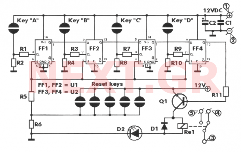
Key Code Combination High Security Door Lock
This project involves an electronic lock that supports numerous combinations, which can be easily modified. It unlocks only with the correct sequence of four consecutive numbers. A significant feature of this electronic lock is that the four numbers must be...

MOSQUITO REPELLANT by IC 555 4017 4011
This is a circuit for a mosquito repellent that operates using high-frequency sound. It utilizes commonly available and low-cost electronic components. The circuit includes integrated circuits such as the IC 555 and 4017.
The mosquito repellent circuit employs a high-frequency sound...
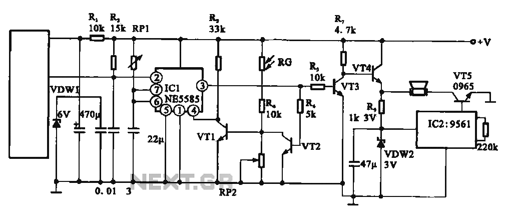
Automated Attendant burglar alarm circuit
This circuit illustrates an automatic unattended burglar alarm system designed primarily for residential use, warehouses, and similar applications. The circuit features a pyroelectric infrared sensor integrated with a light control mechanism. It comprises components such as resistors (RG, RP2, R4),...

FM Moulator with IC 555
The FM modulator circuit is a straightforward FM modulation design utilizing the IC 555, where the resulting modulated signal is dependent on the frequency of the input signal. The output signal is stable and of good quality, eliminating the need...
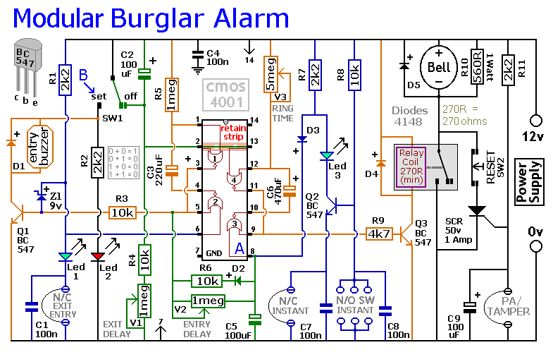
An Expandable Multi-Zone Modular Burglar Alarm circuit
This circuit includes automatic exit and entry delays, as well as a timed bell cut-off feature. It supports both normally-closed and normally-open contacts, and incorporates a 24-hour personal attack/tamper zone. The use of expansion modules allows for the addition of...
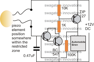
make these simple cheap home burglar
The following article discusses a few very simple intrusion detector circuits, or burglar alarm circuits. The presented designs are straightforward yet highly effective in their functions. The triggering stage may consist of a voltage/current amplifier stage combined with a relay...
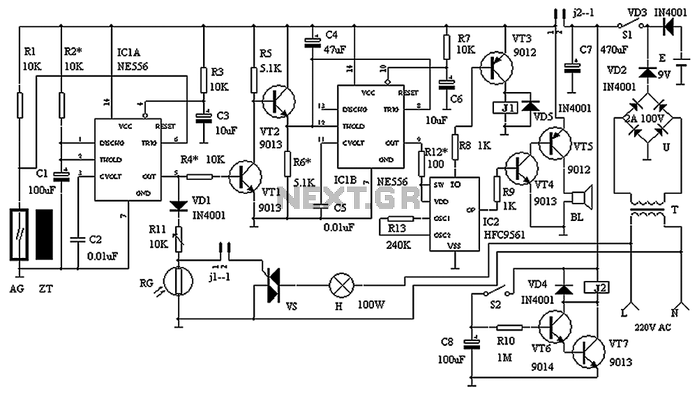
Practical gated burglar alarm circuit diagram
The circuit consists of a triggering device, a monostable delay circuit, an alarm sound generator, an audio amplifier circuit, and a light control circuit, with a partially blocking preset circuit and power circuit. When the door is locked and a...
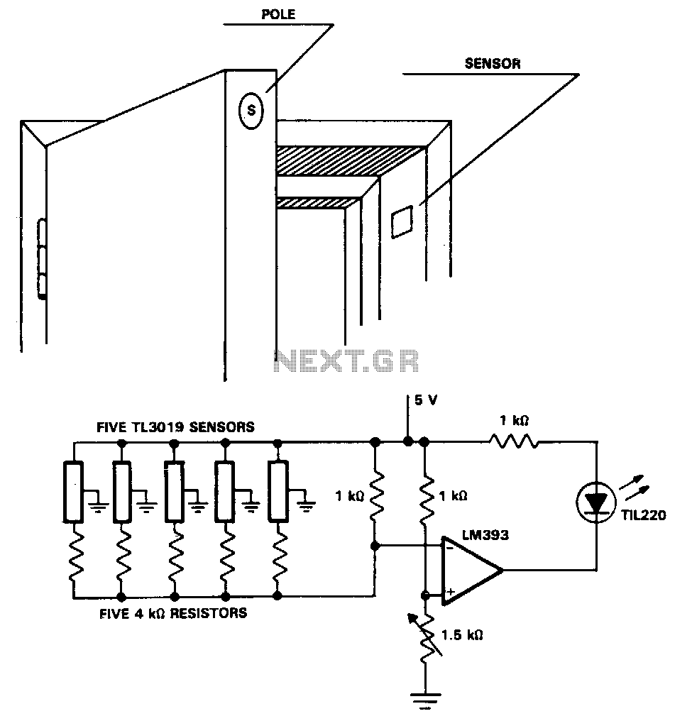
Security-door-ajar-alarm
The TL3019 device activates, or goes low, when a south pole of a magnet approaches the chip face. In this example, there are five doors, each equipped with a magnet embedded in its edge, with the south pole facing outward....
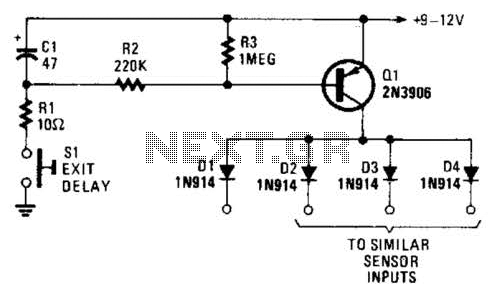
Exit Delay For Burglar Alarms Circuit
Depressing SI charges CI to the supply voltage. This biases Q1 on via bias resistors R2 and R3. A voltage is available for the duration of the delay period to hold off the alarm circuit. CI can be increased or...