


Carrier-Current Baby-Alert Transmitter Circuit
#baby-alert
#transmitter
#LM324
#LMC555CM
#op-amp
#oscillator
#timer
#sound detection
#carrier-current

Description: The baby-alert transmitter is constructed using an LM324 quad operational amplifier (U1), two LMC555CM CMOS oscillator/timers (U2 and U3), along with several supporting components. The transmitter activates upon detecting sound at MIC1, emitting a signal. Its operational frequency is approximately 125 kHz, suitable for triggering an alarm receiver.
The baby-alert transmitter circuit utilizes the LM324 quad op-amp as the primary processing unit, which provides the necessary amplification and signal conditioning. The circuit is designed to monitor ambient sound levels through a microphone (MIC1). When sound is detected, the op-amp amplifies the audio signal, which is then used to trigger the two LMC555CM timers.
The LMC555CM timers are configured in astable mode to generate a continuous square wave signal at a frequency of approximately 125 kHz. This frequency is chosen to ensure effective transmission and minimal interference with other devices. The output from the timers can be connected to an RF transmitter or directly to an alarm receiver, depending on the application requirements.
Supporting components in the circuit include resistors and capacitors that set the gain of the op-amp and determine the timing characteristics of the 555 timers. Proper selection of these components is essential to ensure reliable operation and optimal performance of the transmitter.
Overall, this baby-alert transmitter circuit serves as an efficient solution for monitoring sound levels in environments such as nurseries, providing a means to alert caregivers when a baby is in distress or making noise. The combination of the LM324 op-amp and LMC555CM timers allows for a compact and effective design that can be integrated into various alarm systems. The baby-alert transmitter is built around an LM324 quad op amp (Ul), two LMC555CM CMOS oscillator/timers (U2 and U3), and a few support components. The transmitter sends a signal on receipt of a sound at MIC1. It has a frequency of around 125 kHz and can be used to trigger an alarm receiver.
The baby-alert transmitter circuit utilizes the LM324 quad op-amp as the primary processing unit, which provides the necessary amplification and signal conditioning. The circuit is designed to monitor ambient sound levels through a microphone (MIC1). When sound is detected, the op-amp amplifies the audio signal, which is then used to trigger the two LMC555CM timers.
The LMC555CM timers are configured in astable mode to generate a continuous square wave signal at a frequency of approximately 125 kHz. This frequency is chosen to ensure effective transmission and minimal interference with other devices. The output from the timers can be connected to an RF transmitter or directly to an alarm receiver, depending on the application requirements.
Supporting components in the circuit include resistors and capacitors that set the gain of the op-amp and determine the timing characteristics of the 555 timers. Proper selection of these components is essential to ensure reliable operation and optimal performance of the transmitter.
Overall, this baby-alert transmitter circuit serves as an efficient solution for monitoring sound levels in environments such as nurseries, providing a means to alert caregivers when a baby is in distress or making noise. The combination of the LM324 op-amp and LMC555CM timers allows for a compact and effective design that can be integrated into various alarm systems. The baby-alert transmitter is built around an LM324 quad op amp (Ul), two LMC555CM CMOS oscillator/timers (U2 and U3), and a few support components. The transmitter sends a signal on receipt of a sound at MIC1. It has a frequency of around 125 kHz and can be used to trigger an alarm receiver.
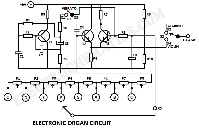
Electronic Organ Circuit
This electronic organ circuit is straightforward to construct and primarily consists of an emitter-coupled oscillator formed by transistors T2 and T3. A square wave voltage can be obtained from the collector of T3 (X2), which imparts a clarinet-like quality to...
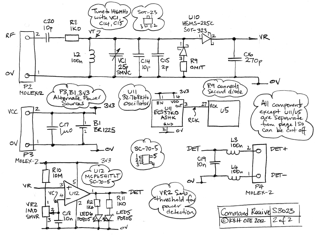
Command Transmitter-Receiver
The Command Transmitter-Receiver (A3023) is designed to test the command receiver proposed for the Implantable Sensor with Lamp (ISL) in the conceptual design phase. The A3023 consists of two primary components: the Command Transmitter section, which features a 146-MHz (2-m...
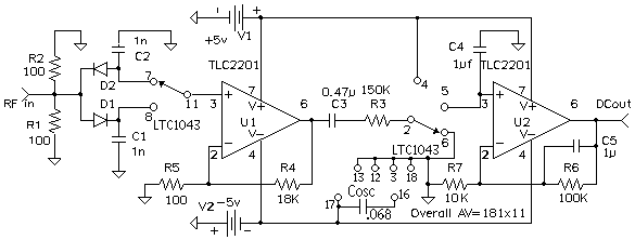
Amplifying DC Diode Detector Output
The small DC voltages at the output of the diode detector are challenging to amplify accurately due to DC offsets introduced by any operational amplifier (op-amp) and low-frequency noise (1/f noise). A solution to these issues is to chop the...
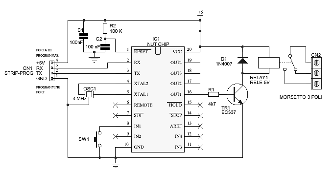
Timer circuit
The schematic diagram is straightforward. SW1 is a pushbutton used to start the timer. The outputs are set to logic level 0 when the timer is inactive and to logic level 1 when the timer is triggered. The relay driver...
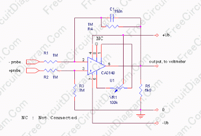
Single Differential Input Adapter for Digital Voltmeter
In some cases, a cogwheel input is necessary for voltage measurement. By utilizing a single operational amplifier, an adapter can be created to accommodate a differential input for a ground-referenced voltmeter. It is recommended to use 1% tolerance metal film...
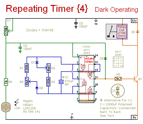
Repeating Timer 4
This circuit is the inverse of Repeating Timer No. 3. Its operation can be restricted to nighttime hours. The variable resistor (preset) allows selection of the darkness level at which the timer will activate.
The described circuit functions as a light-activated...
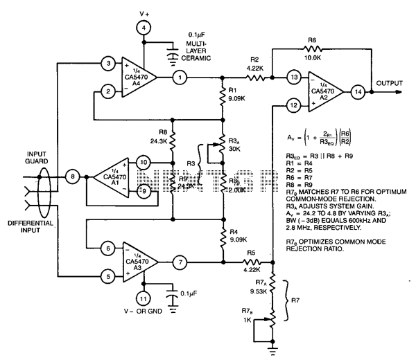
Differential-to-single-ended-voltage-amplifier
This circuit utilizes a CA5470 quad microprocessor BiMOS-E operational amplifier. Amplifiers A1 and A2 are configured as a cross-coupled differential input and differential output preamplifier stage, while A3 is responsible for input guard-banding. Additionally, amplifier A4 converts the differential outputs...
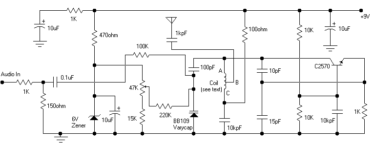
Colpitts oscillator FM transmitter
Its frequency depends on the capacitance of the vary cap diode. The center frequency is changed by varying the biasing voltage of the vary cap through the 47K pot. You can use a 75cm telescopic antenna or simply a length...
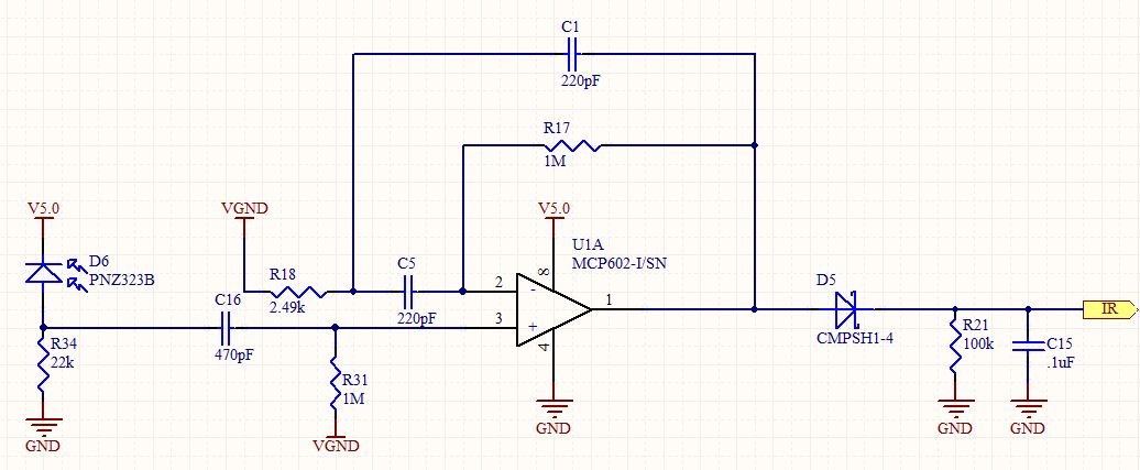
op amp IR Demodulator Design
Designing an infrared (IR) demodulator circuit to replace the one shown in this question. The goal is to demodulate a simple IR signal modulated at 32.678 kHz, with the requirement of detecting the presence of the signal without packet decoding....