


Current-monitor-and-alarm
#current monitor
#signal lamp
#transistor
#diode
#fuse
#1N400x
#1N540x
#alarm circuit
#current detection
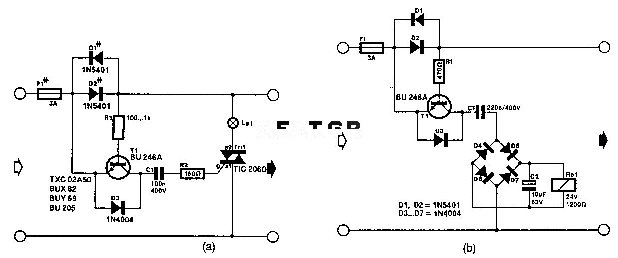
Description: The circuit in Fig. 56-lla activates a signal lamp when it detects a line current consumption exceeding 5 mA and can handle currents of several amperes using suitable diodes in the D1 and D2 positions. Transistor T1 is activated when the voltage drop across D1 and D2 surpasses a specific threshold. Diodes from the widely used 1N400x series can accommodate currents up to 1 A, while the 1N540x series is rated for currents up to 3 A. Fuse F1 must be selected based on the specific application. The circuit in Fig. 56-llb functions as a current-triggered alarm. The rectifier bridge formed by diodes D4 through D7 supplies voltage to the relay coil Rel only when the current through D1 and D2 exceeds a predetermined level, allowing series capacitor C1 to pass the alternating main current. The value of capacitor C1 must be chosen to match the sensitivity requirements of the relay coil. This can be achieved by connecting multiple capacitors in parallel until the voltage across the coil is sufficient for reliable relay operation.
The circuit depicted in Fig. 56-lla serves as a current monitoring and signaling device. It is designed to illuminate a signal lamp when the current consumption exceeds 5 mA, indicating that the monitored circuit is active. The diodes D1 and D2 play a crucial role in this circuit, as they must be selected to handle the maximum expected current. The 1N400x series diodes are suitable for applications up to 1 A, while the 1N540x series can accommodate higher currents, up to 3 A. The transistor T1 acts as a switch, turning on when the voltage drop across D1 and D2 reaches the required level, thus triggering the signal lamp.
In Fig. 56-llb, the current-triggered alarm circuit is designed to activate a relay based on the current flowing through diodes D1 and D2. The rectifier bridge composed of diodes D4 through D7 converts the alternating current into direct current, allowing the relay coil Rel to be energized only when the current exceeds a certain threshold. The series capacitor C1 is essential for the operation of this circuit, as it enables the passage of the alternating current to the relay coil. The selection of C1 is critical, as it must be sensitive enough to allow the relay to activate reliably. To achieve the desired capacitance, multiple capacitors can be connected in parallel, which increases the total capacitance until the voltage across the relay coil reaches the operational level required for reliable activation.
Overall, these circuits exemplify the integration of basic electronic components to create functional monitoring and control systems, capable of responding to specific current levels in various applications. Proper selection of components, such as diodes and capacitors, is essential for ensuring reliable operation and performance in the intended environment.The circuit in Fig. 56-lla lights the signal lamp upon detecting a line current consumption of more than 5 mA, and handles currents of several amperes with appropriate diodes fitted in the D1 and D2 positions. Transistor T1 is switched on when the drop across Dl/D2 exceeds a certain level. Diodes from the well-known 1N400x series can be used for currents of up to 1 A, while 1N540x types are rated for up to 3A.
Fuse F1 should suit the particuiar application. The circuit in Fig. 56-llb is a current-triggered alarm. Rectifier bridge D4 through D7 can only provide the coil voltage for Rel when the current through D1/D2 exceeds a certain level, because then series capacitor C1 passes the alternating main current. Capacitor C1 needs to suit the sensitivity of the relay coil. This is readily effected by connecting capacitors in parallel until the coil voltage is high enough for the relay to operate reliably.
The circuit depicted in Fig. 56-lla serves as a current monitoring and signaling device. It is designed to illuminate a signal lamp when the current consumption exceeds 5 mA, indicating that the monitored circuit is active. The diodes D1 and D2 play a crucial role in this circuit, as they must be selected to handle the maximum expected current. The 1N400x series diodes are suitable for applications up to 1 A, while the 1N540x series can accommodate higher currents, up to 3 A. The transistor T1 acts as a switch, turning on when the voltage drop across D1 and D2 reaches the required level, thus triggering the signal lamp.
In Fig. 56-llb, the current-triggered alarm circuit is designed to activate a relay based on the current flowing through diodes D1 and D2. The rectifier bridge composed of diodes D4 through D7 converts the alternating current into direct current, allowing the relay coil Rel to be energized only when the current exceeds a certain threshold. The series capacitor C1 is essential for the operation of this circuit, as it enables the passage of the alternating current to the relay coil. The selection of C1 is critical, as it must be sensitive enough to allow the relay to activate reliably. To achieve the desired capacitance, multiple capacitors can be connected in parallel, which increases the total capacitance until the voltage across the relay coil reaches the operational level required for reliable activation.
Overall, these circuits exemplify the integration of basic electronic components to create functional monitoring and control systems, capable of responding to specific current levels in various applications. Proper selection of components, such as diodes and capacitors, is essential for ensuring reliable operation and performance in the intended environment.The circuit in Fig. 56-lla lights the signal lamp upon detecting a line current consumption of more than 5 mA, and handles currents of several amperes with appropriate diodes fitted in the D1 and D2 positions. Transistor T1 is switched on when the drop across Dl/D2 exceeds a certain level. Diodes from the well-known 1N400x series can be used for currents of up to 1 A, while 1N540x types are rated for up to 3A.
Fuse F1 should suit the particuiar application. The circuit in Fig. 56-llb is a current-triggered alarm. Rectifier bridge D4 through D7 can only provide the coil voltage for Rel when the current through D1/D2 exceeds a certain level, because then series capacitor C1 passes the alternating main current. Capacitor C1 needs to suit the sensitivity of the relay coil. This is readily effected by connecting capacitors in parallel until the coil voltage is high enough for the relay to operate reliably.
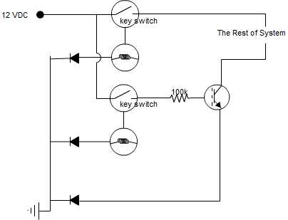
transistor as a switch circuit problems
A circuit is being designed that incorporates two key switches, which must both be closed for current to flow through the circuit.
The proposed circuit configuration employs two key switches connected in series. In this arrangement, the current can only pass...
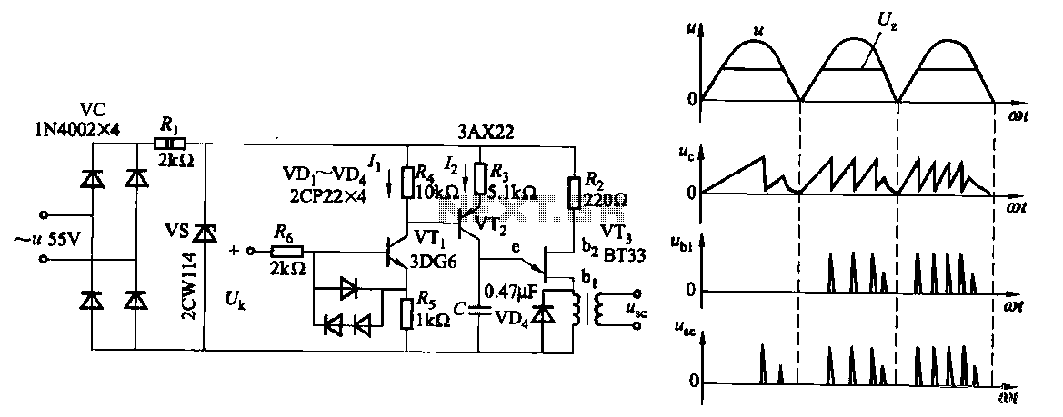
Single-junction transistor trigger circuit 2
Due to the increased level of the transistor amplifier circuit, the control circuit's performance in Figure 16-6 is more sensitive and can accept input control signals superimposed on others (such as voltage, current, and speed feedback signals) to meet system...
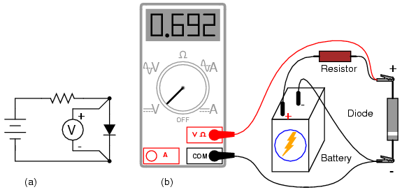
Meter check of a diode
Understanding the polarity (cathode versus anode) and basic functionality of a diode is an essential skill for electronics hobbyists or technicians. A diode acts like a one-way valve for electricity, and its one-way nature can be verified using a DC...
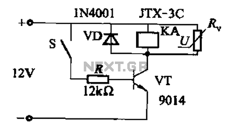
Fast response time of the control transistor circuit b
In a concrete circuit relay application, the transistor VT functions as a high-speed, high-voltage switch. The voltage requirement for switching is 5 to 10 times the rated voltage of the solenoid valve. The circuit is designed for a fast response...
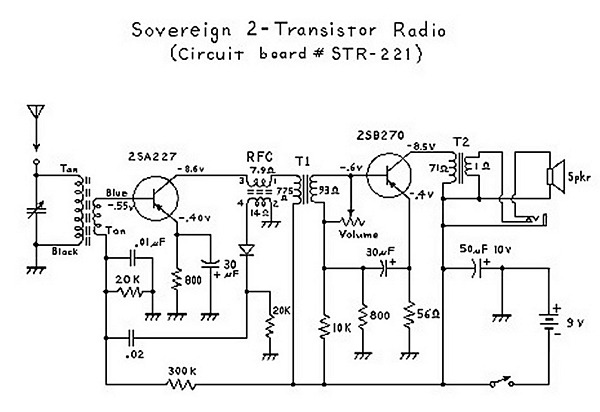
Two Transistor (Boys Radio) Schematic and Theory of Operation
An analysis of certain radios reveals the impressive engineering by Japanese designers, particularly in creating a radio capable of driving a speaker with only two transistors. The first transistor (Q1) serves a dual function; it operates as an RF amplifier...
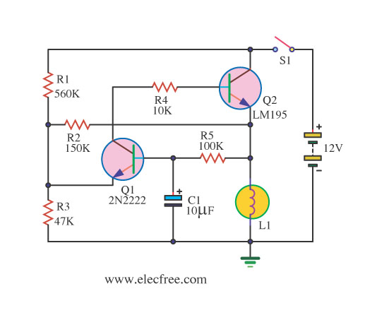
A lamp flasher circuit using transistors
If you require a small lamp that flashes for general use, there are numerous options available. Today, three lamp flasher circuits will be presented.
The three lamp flasher circuits can be designed using different components and configurations, each offering unique characteristics...
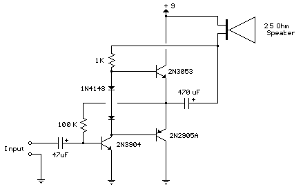
improved 3 transistor audio amp
This circuit is similar to the previous one but employs positive feedback to enhance the amplitude delivered to the speaker. It is adapted from a small 5-transistor radio that utilizes a 25-ohm speaker. In the earlier circuit, the load resistor...
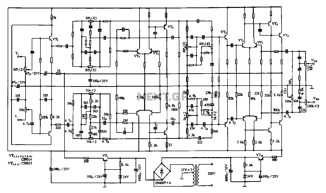
Transistor attenuation - feedback tone circuit
Figure 4-11 illustrates a feedback attenuator that comprises a transistor-based tone control circuit. This circuit features a conventional high and bass control system, along with balance control, volume control, loudness adjustment, and subwoofer control, as well as field sense control....
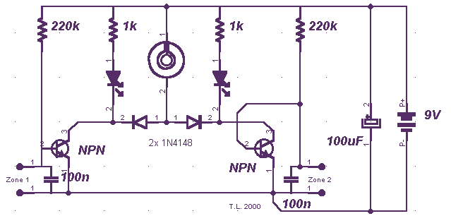
Miniature Loop Alarm
Simple construction, reliable operation, very small power consumption, and, most of all, small size. I started with CMOS logic gates, but was soon forced to abandon the concept after a few unsuccessful (and far too complicated) attempts. Then I suddenly...