


Domestic Seismic Alarm
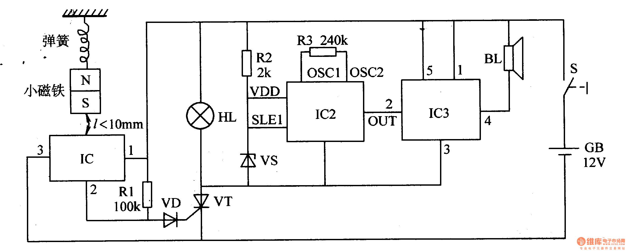
Description: When the switch is activated, the seismic alarm enters a detection mode. In the absence of an earthquake, pin 3 of IC1 outputs a low signal, resulting in the disconnection of VT, which keeps the alarm circuit inactive. Upon the occurrence of an earthquake, the magnet shifts vertically. As it moves away from IC1, pin 3 of IC1 outputs a high signal, connecting VT and illuminating HL. Subsequently, IC2 and IC3 are activated. The sound signal generated by IC2 is amplified by IC3, causing BL to emit an alarm sound.
The seismic alarm circuit consists of several key components that work together to detect seismic activity and trigger an alarm. The core of the system is IC1, which serves as the primary detection unit. When the switch is turned on, it enables the detection mode, allowing the circuit to monitor for seismic events.
In its idle state, when no earthquake is detected, IC1's pin 3 remains low, ensuring that VT (which may represent a relay or transistor) is not activated. This state prevents any current from flowing through the alarm circuit, keeping the system in a standby mode. The magnet is positioned close to IC1, maintaining a stable state.
Upon the detection of seismic activity, the magnet's movement causes it to shift vertically. This movement alters the magnetic field around IC1, prompting pin 3 to switch to a high state. This transition activates VT, allowing current to flow through the circuit and illuminating HL, which likely serves as a visual indicator of an alarm condition.
With VT activated, additional integrated circuits IC2 and IC3 come into play. IC2 is responsible for generating an audio signal in response to the detected seismic activity. This signal is then sent to IC3, which functions as an audio amplifier. IC3 boosts the sound output from IC2, ensuring that the alarm sound produced by BL (the buzzer or speaker) is loud enough to alert individuals in the vicinity of the seismic event.
Overall, the circuit is designed to provide a reliable alarm system for detecting earthquakes, combining visual and auditory signals to ensure effective communication of the alarm condition. The integration of multiple ICs allows for efficient processing of seismic signals and amplification of the alarm sound, enhancing the system's responsiveness and reliability.When the switch is on, the seismic alarm isin detection condition. When there is no earthquake, IC1`s pin 3 outputs low level and VT is disconnected. The alarm circuit does not work. When there is an earthquake, the magnet will move vertically. When it is away from IC1, IC1`s pin 3 outputs high level and VT is connected. HL is illuminated. IC2 and IC3 begin to work. When the sound signal output by IC2 is amplified by IC3, BL will make an alarm sound.
The seismic alarm circuit consists of several key components that work together to detect seismic activity and trigger an alarm. The core of the system is IC1, which serves as the primary detection unit. When the switch is turned on, it enables the detection mode, allowing the circuit to monitor for seismic events.
In its idle state, when no earthquake is detected, IC1's pin 3 remains low, ensuring that VT (which may represent a relay or transistor) is not activated. This state prevents any current from flowing through the alarm circuit, keeping the system in a standby mode. The magnet is positioned close to IC1, maintaining a stable state.
Upon the detection of seismic activity, the magnet's movement causes it to shift vertically. This movement alters the magnetic field around IC1, prompting pin 3 to switch to a high state. This transition activates VT, allowing current to flow through the circuit and illuminating HL, which likely serves as a visual indicator of an alarm condition.
With VT activated, additional integrated circuits IC2 and IC3 come into play. IC2 is responsible for generating an audio signal in response to the detected seismic activity. This signal is then sent to IC3, which functions as an audio amplifier. IC3 boosts the sound output from IC2, ensuring that the alarm sound produced by BL (the buzzer or speaker) is loud enough to alert individuals in the vicinity of the seismic event.
Overall, the circuit is designed to provide a reliable alarm system for detecting earthquakes, combining visual and auditory signals to ensure effective communication of the alarm condition. The integration of multiple ICs allows for efficient processing of seismic signals and amplification of the alarm sound, enhancing the system's responsiveness and reliability.When the switch is on, the seismic alarm isin detection condition. When there is no earthquake, IC1`s pin 3 outputs low level and VT is disconnected. The alarm circuit does not work. When there is an earthquake, the magnet will move vertically. When it is away from IC1, IC1`s pin 3 outputs high level and VT is connected. HL is illuminated. IC2 and IC3 begin to work. When the sound signal output by IC2 is amplified by IC3, BL will make an alarm sound.
House Alarm Loop
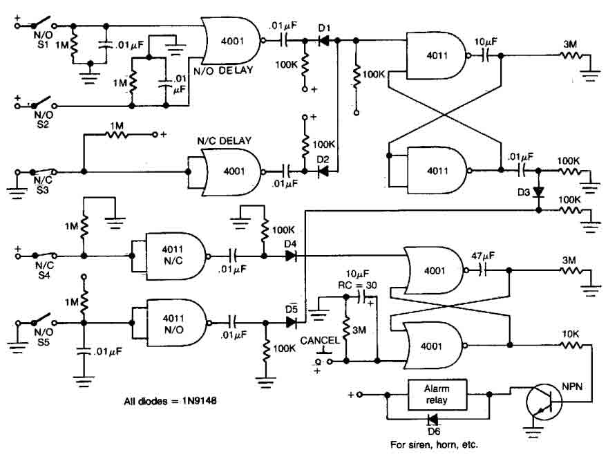
This circuit features open and closed loop contacts (switches 1, 2, 3) that activate the alarm, which remains activated for 5 to 10 minutes. The triggering delay for entrance and exit is set to 27 seconds. Additionally, this simple alarm...
House Alarm Loop
This circuit features open and closed loop contacts (switches 1, 2, 3) that activate the alarm, which remains activated for 5 to 10 minutes. The triggering delay for entrance and exit is set to 27 seconds. Additionally, this simple alarm...
A three-alarm phase circuits
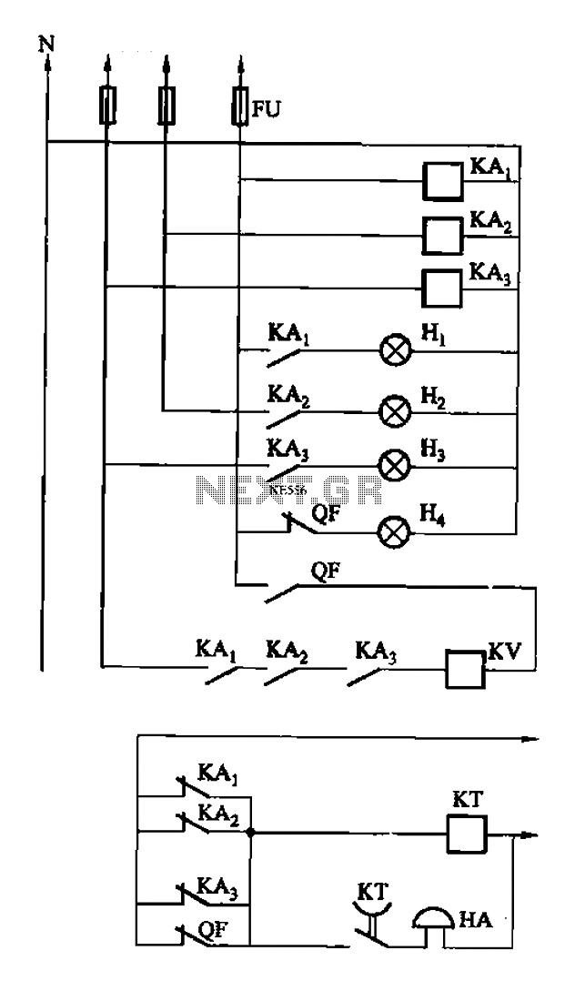
The circuit features intermediate relays KAi, KA2, and KA3, which are connected to the outlet end of the low-voltage circuit breakers. An alarm circuit is linked to a backup power supply or a battery power supply. This configuration serves to...
5 Zone Alarm Circuit
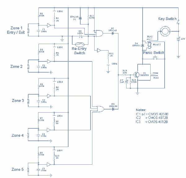
Each zone uses a normally closed contact. These can be micro switches or standard alarm contacts (usually reed switches). Zone 1 is a timed zone which must be used as the entry and exit point of the building. Zones 2...

High-Output Pulsed-Tone/Light-Activated Alarm Circuit
This circuit is capable of generating up to 1 W of audio power to drive a speaker or horn. When the CDS cell is exposed to light, its resistance decreases, activating NOR gate (a). This activation causes gates (a) and...

Induction high pressure alarm circuit
It utilizes the KD153 type "ding-dong" music integrated circuit (IC) to produce a "ding-dong" sound alarm. The reference number is 221611, and it is related to a refrigerator door alarm circuit.
The KD153 integrated circuit is designed specifically for generating melodic...
Simple 6-Input Alarm
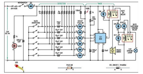
This simple alarm circuit was designed for use in a combined garage and rumpus room. It can be assembled on Veroboard and uses just one IC plus a handful of additional components.
The alarm circuit is based on a single integrated...
5 Zone Alarm Circuit
Each zone uses a normally closed contact. These can be micro switches or standard alarm contacts (usually reed switches). Zone 1 is a timed zone which must be used as the entry and exit point of the building. Zones 2...
Elderly lost alarm circuit
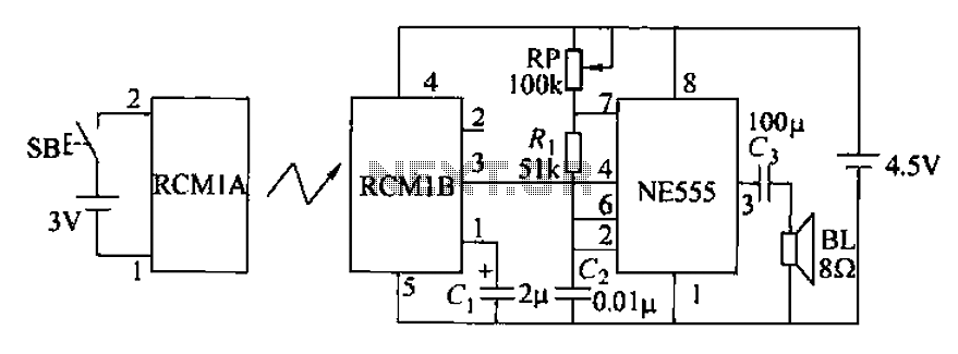
The circuit utilizes an RMIB multivibrator component that operates at a maximum distance. When the distance exceeds a specific threshold, the output pin of the receiver goes low, effectively stopping the oscillation. The NE555 multivibrator, which is part of the...