


Door alarm circuit with a time of recognition NE555
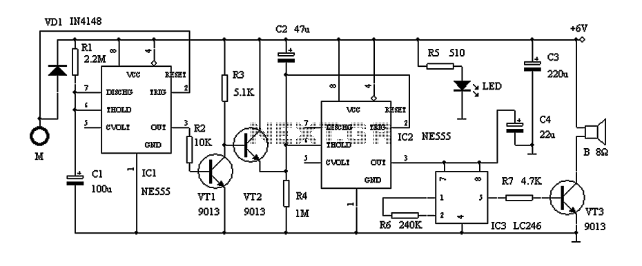
Description: This circuit describes a door alarm system equipped with a time recognition feature. When the owner opens the door, it remains in a normal state for approximately 30 seconds without triggering the alarm. However, if the door is opened by an unauthorized individual or if it remains open for more than 30 seconds, the alarm will activate, providing significant practical value. The circuit, illustrated in Figure 1, primarily consists of a 555 timer IC (IC1) configured as a monostable multivibrator, with associated resistors (R1) and capacitors (C1) to set a transient time of approximately 4 minutes. Under normal conditions, IC1 outputs a low signal, keeping transistor VT1 off and transistor VT2 conducting, which shorts capacitor C2 to prevent it from charging. Consequently, the threshold pin of IC2 remains low, preventing the alarm sound integrated circuit (IC3) from activating, thus keeping the speaker silent. A touchpad (M) is connected to the metal door. When someone attempts to unlock the door, the touchpad triggers IC1, putting it into a transient state and causing its output to go high. This action turns on transistor VT1 and turns off VT2, allowing capacitor C2 to charge through resistor R4. As the charging time extends, the voltage at IC2's pin decreases until it exceeds the threshold after approximately 30 seconds, causing IC2 to output a high signal and activate IC3, which triggers the alarm. If the door remains open for less than 30 seconds, IC2 stays low, and the circuit does not trigger the alarm. The duration of the alarm sound (T1) is determined by the transient time of IC1, which is set to approximately 4 minutes. After this period, IC1's output reverts to low, turning off VT1, allowing VT2 to conduct and deactivate IC3, silencing the alarm. If the door is touched again after 30 seconds, the alarm circuit will reinitiate. The system is powered by a battery pack consisting of four batteries in series; however, a capacitor step-down power supply circuit must not be used to prevent electric shock.
The door alarm circuit employs a 555 timer IC configured in monostable mode, which allows for a simple yet effective timing mechanism. The resistor R1 and capacitor C1 together determine the timing interval for the alarm system. The output of the 555 timer is responsible for controlling the state of the transistors VT1 and VT2, which manage the charging of capacitor C2 and the activation of the alarm sound circuit.
Transistor VT1 acts as a switch that, when activated, allows current to flow to the alarm circuit, while VT2 serves to short capacitor C2, preventing it from charging until the door is manipulated. The touchpad (M) provides a user interface that detects when the door is being opened. The alarm condition is triggered when the door remains open past the designated time limit, which is adjustable by changing the values of R1 and C1.
The integrated circuit IC3, which is the alarm sound generator, remains inactive until a high signal is received from IC2, indicating that the door has been left open for too long. The system's design incorporates safety measures to ensure that it operates effectively without posing a risk of electric shock, highlighting the importance of using appropriate power supply methods. This door alarm circuit is suitable for residential or commercial applications, providing an additional layer of security against unauthorized access.Door alarm here with a time recognition, the owner opened the door is normally open the door, open the door to complete the action within the general 30s, so it does not alarm, tried to open the door to strangers or thieves breaking open the door is not normal, usually a longer time, Once more than 30s, it will sound an alarm, it has great practical value.Circuit shown in Figure 1, mainly by the 555 IC alarm IC components.Timebase circuit IC1 and R1, C1 composition transient time T monoflop 4min around, usually IC1 at steady state, the pin output low, VT1 off, VT2 conduction, the capacitor C2 is shorted VT2 It can not be charged when the base circuit IC2 threshold terminal feet high, pin output low, the alarm sound integrated circuit IC3 does not work without power supply, speaker B silent.M is a touch pads, connected with a metal door. When someone unlocking Chung Ning apricot µ brain hard µ mother shouted shin Xiang and C1 trigger end feet, IC1 into the transient, pin output high, then the transistor conduction VT1, VT2 off, power can charging of C2 through R4, with the extension of the charging time, feet IC2 potential declining after about 30s, IC2 flip it feet high output, so IC3 electrical work alarm.
If the open time in less than 30s, then the IC2 pin is low, the circuit will not alarm. Alarm sound duration T1 determined by IC1 transient time, T1 1.1R1 C1 4min, 4min after, feet of IC1 output low, VT1 off, VT2 conduction, IC3 power failure, the alarm sound stops. If you touch door over 30s again, but again the alarm circuit.Battery power is available (four batteries in series) power supply, but must not use capacitor step-down power supply circuit to avoid electric shock!
The door alarm circuit employs a 555 timer IC configured in monostable mode, which allows for a simple yet effective timing mechanism. The resistor R1 and capacitor C1 together determine the timing interval for the alarm system. The output of the 555 timer is responsible for controlling the state of the transistors VT1 and VT2, which manage the charging of capacitor C2 and the activation of the alarm sound circuit.
Transistor VT1 acts as a switch that, when activated, allows current to flow to the alarm circuit, while VT2 serves to short capacitor C2, preventing it from charging until the door is manipulated. The touchpad (M) provides a user interface that detects when the door is being opened. The alarm condition is triggered when the door remains open past the designated time limit, which is adjustable by changing the values of R1 and C1.
The integrated circuit IC3, which is the alarm sound generator, remains inactive until a high signal is received from IC2, indicating that the door has been left open for too long. The system's design incorporates safety measures to ensure that it operates effectively without posing a risk of electric shock, highlighting the importance of using appropriate power supply methods. This door alarm circuit is suitable for residential or commercial applications, providing an additional layer of security against unauthorized access.Door alarm here with a time recognition, the owner opened the door is normally open the door, open the door to complete the action within the general 30s, so it does not alarm, tried to open the door to strangers or thieves breaking open the door is not normal, usually a longer time, Once more than 30s, it will sound an alarm, it has great practical value.Circuit shown in Figure 1, mainly by the 555 IC alarm IC components.Timebase circuit IC1 and R1, C1 composition transient time T monoflop 4min around, usually IC1 at steady state, the pin output low, VT1 off, VT2 conduction, the capacitor C2 is shorted VT2 It can not be charged when the base circuit IC2 threshold terminal feet high, pin output low, the alarm sound integrated circuit IC3 does not work without power supply, speaker B silent.M is a touch pads, connected with a metal door. When someone unlocking Chung Ning apricot µ brain hard µ mother shouted shin Xiang and C1 trigger end feet, IC1 into the transient, pin output high, then the transistor conduction VT1, VT2 off, power can charging of C2 through R4, with the extension of the charging time, feet IC2 potential declining after about 30s, IC2 flip it feet high output, so IC3 electrical work alarm.
If the open time in less than 30s, then the IC2 pin is low, the circuit will not alarm. Alarm sound duration T1 determined by IC1 transient time, T1 1.1R1 C1 4min, 4min after, feet of IC1 output low, VT1 off, VT2 conduction, IC3 power failure, the alarm sound stops. If you touch door over 30s again, but again the alarm circuit.Battery power is available (four batteries in series) power supply, but must not use capacitor step-down power supply circuit to avoid electric shock!
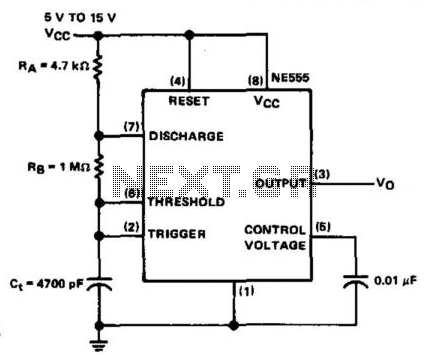
Square-Wave Oscillator
The NE555 timer is configured in astable mode and utilizes three timing components (RA, RB, and Ct). A 0.01 µF bypass capacitor is connected to pin 5 to enhance noise immunity. The operational limitations of the astable mode are minimal....
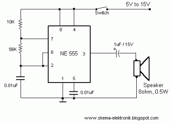
Electronic Buzzer with IC timer NE555 circuit diagram
This easy electronic buzzer circuit is built based on a timer that operates to generate frequency. The IC timer NE555 is used as an astable multivibrator operating at approximately 1 kHz, producing a sound when powered on. The sound frequency...
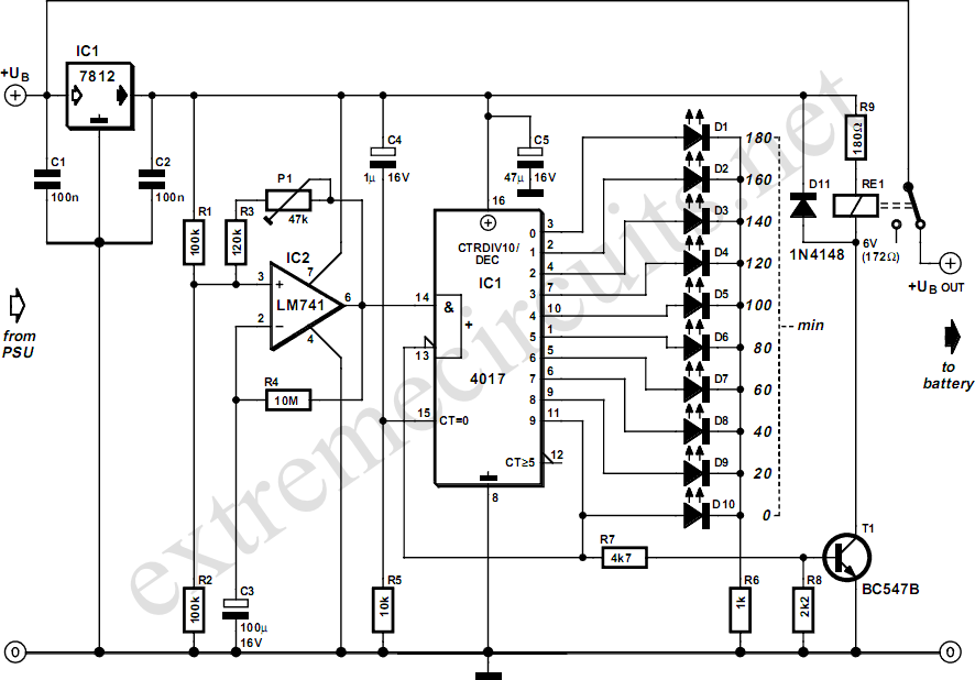
Three Hour Timer
Manufacturers of cordless drills typically recommend a battery charging time of three hours. Once this charging time is complete, the battery must be disconnected from the charger to prevent the risk of overcharging. This circuit, positioned between the charger and...
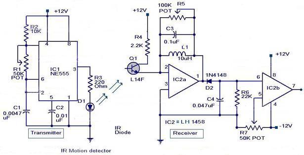
NE555 IC For Infrared Motion Sensor
The following circuit illustrates an Infrared Motion Sensor circuit diagram. Features include the use of the NE555 integrated circuit, with a detection zone coverage of 80 degrees.
The Infrared Motion Sensor circuit utilizes the NE555 timer IC configured in a monostable...
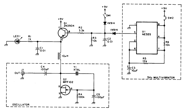
SHORTWAVE PULSED MARKER OSCILLATOR
A marker oscillator can be constructed using an NE555 timer to generate pulses at an audio frequency. This design facilitates the identification of signals amidst interference. The oscillator can utilize a crystal with a frequency ranging from 1 to 30...
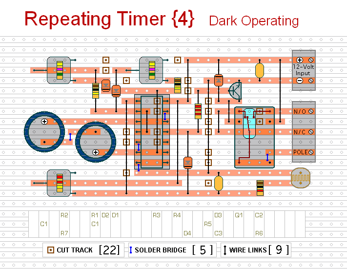
repeating timer no4
This circuit functions as the inverse of Repeating Timer No. 3. Its operation is constrained to the hours of darkness. The variable resistor (preset) allows for the selection of the darkness level at which the timer will activate.
The circuit is...
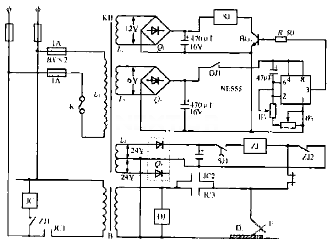
A welding load automatic power-off circuit
The NE555 timer circuit functions as a vibration generator. The input pin 3 produces pulse frequencies ranging from 5 to 20 Hz. The circuit includes a fan that operates within a bamboo enclosure. The barrel section is designed to accommodate...
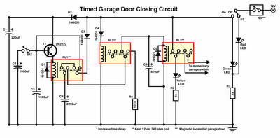
Timer Garage Door Circuit Schematic Diagram
Timer garage door circuit schematic diagram, printed circuit board.
The timer garage door circuit is designed to automate the opening and closing of a garage door based on a predetermined time interval. The schematic diagram illustrates the layout and connections of...
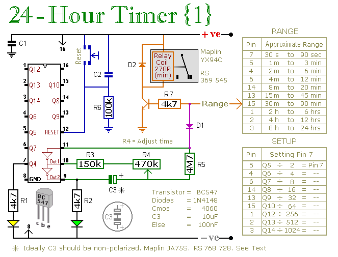
24 Hour Timer
These two circuits are multi-range timers that offer periods of up to 24 hours and beyond. Both circuits are fundamentally similar, with the key distinction being that Version 1 energizes the relay when the time expires, while Version 2 de-energizes...