


Door Bell Circuit Using BEL 188 PCB
#door bell
#BEL 188
#transistor
#push-pull amplifier
#low cost
#sound
#PNP transistor
#calling bell
#DIY
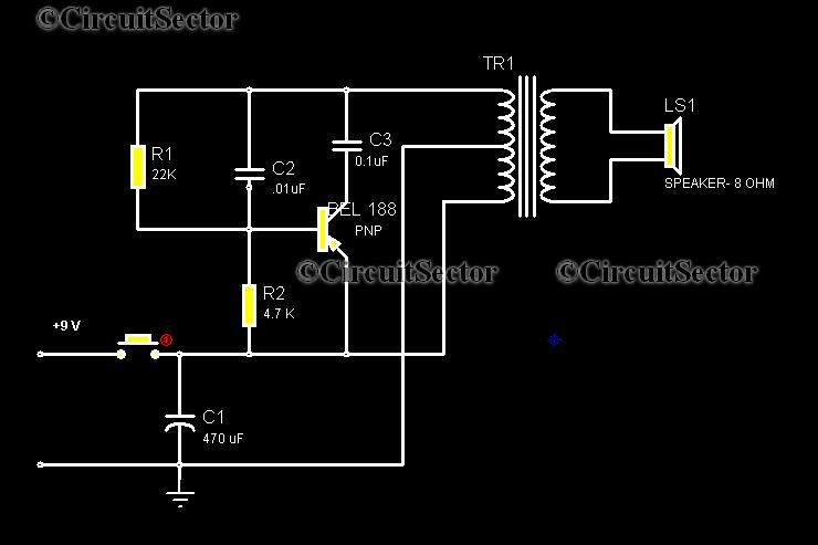
Description: This circuit is a low-cost, one-touch doorbell using a Bel 188 transistor. It is likely one of the most economical bell circuits that can be constructed. The core component of this circuit is the output transformer from a push-pull amplifier, commonly found in transistor radios, along with a Bel 188 PNP transistor. The sound produced by this doorbell circuit resembles a machine gun and activates whenever the switch is pressed. The sound begins loudly and gradually fades to silence. The circuit can be assembled on a standard PCB. It is designed to operate on a 9-volt supply, although it can function at lower voltages with a slight reduction in volume.
This low-cost doorbell circuit utilizes a Bel 188 PNP transistor, which acts as the primary switching element. The circuit design incorporates a push-pull amplifier output transformer, which is integral for generating the sound output. When the switch is activated, the transistor conducts, allowing current to flow through the transformer. This action generates an audible signal that begins at a high volume and tapers off, creating a distinctive sound effect reminiscent of a machine gun.
The circuit's design allows for flexibility in power supply. Although it is optimized for a 9-volt supply, it can operate at lower voltages, such as 6 volts, with a corresponding decrease in sound intensity. This adaptability makes it suitable for various applications where power supply options may vary.
Assembly of the circuit is straightforward, as it can be mounted on a standard printed circuit board (PCB). This feature simplifies the construction process and enhances the reliability of the connections. The components required for this circuit are readily available, making it an accessible project for both novice and experienced electronics enthusiasts.
In summary, this one-touch doorbell circuit is an economical solution for creating an audible alert system. Its unique sound profile, combined with its simple construction and adaptability to various voltage levels, makes it a practical choice for a wide range of applications.Circuit Here is a low cost one touch door bell circuit using Bel 188 transistor. I think this may be the most cheap bell circuit that can be made. The core of this circuit is a output transformer of push-pull amplifier that often used in transistor radios and a Bel 188 PNP transistor. The sound produced from the circuit of calling bell is a machin e gun like and it produces when ever we press the switch. It starts from loud and then fade out to silence. The circuit can be assembled on a common PCB. This door bell circuit is designed to work on a 9 Volt supply but it may works even low voltages at the cost of slightly reduced volume.
This low-cost doorbell circuit utilizes a Bel 188 PNP transistor, which acts as the primary switching element. The circuit design incorporates a push-pull amplifier output transformer, which is integral for generating the sound output. When the switch is activated, the transistor conducts, allowing current to flow through the transformer. This action generates an audible signal that begins at a high volume and tapers off, creating a distinctive sound effect reminiscent of a machine gun.
The circuit's design allows for flexibility in power supply. Although it is optimized for a 9-volt supply, it can operate at lower voltages, such as 6 volts, with a corresponding decrease in sound intensity. This adaptability makes it suitable for various applications where power supply options may vary.
Assembly of the circuit is straightforward, as it can be mounted on a standard printed circuit board (PCB). This feature simplifies the construction process and enhances the reliability of the connections. The components required for this circuit are readily available, making it an accessible project for both novice and experienced electronics enthusiasts.
In summary, this one-touch doorbell circuit is an economical solution for creating an audible alert system. Its unique sound profile, combined with its simple construction and adaptability to various voltage levels, makes it a practical choice for a wide range of applications.Circuit Here is a low cost one touch door bell circuit using Bel 188 transistor. I think this may be the most cheap bell circuit that can be made. The core of this circuit is a output transformer of push-pull amplifier that often used in transistor radios and a Bel 188 PNP transistor. The sound produced from the circuit of calling bell is a machin e gun like and it produces when ever we press the switch. It starts from loud and then fade out to silence. The circuit can be assembled on a common PCB. This door bell circuit is designed to work on a 9 Volt supply but it may works even low voltages at the cost of slightly reduced volume.
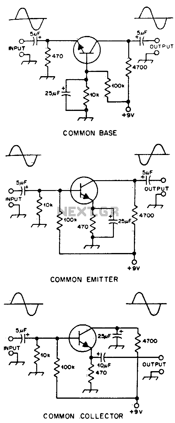
Basic transistor amplifier circuits
Typical component values are provided for use at audio frequencies, where these circuits are most commonly utilized. The input and output phase relationships are illustrated.
The circuit design focuses on audio frequency applications, emphasizing the selection of component values that optimize...
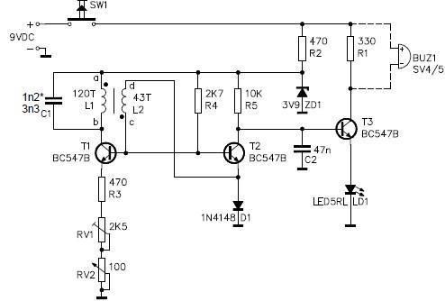
Metal detector circuit electronic project using transistors
This metal detector circuit project is a simple design based on common electronic components. It utilizes transistors to provide a visual indication through an LED and an acoustic signal to alert users when metal is detected. To calibrate the circuit,...

turret diy
For maximum mini-security, this RC Tupperware Turret delivers a formidable deterrent against food theft. While it lacks motion sensors, potential food thieves will think twice before attempting to swipe baked goods. This 11-hour project, designed by Chris of PyroElectro, emphasizes...
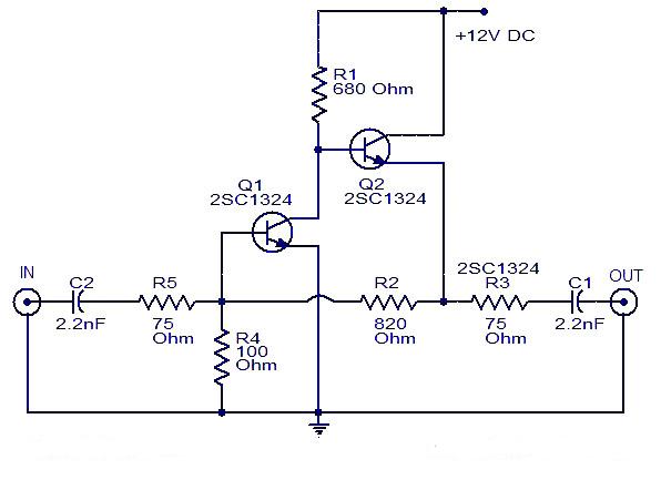
Cable TV amplifier Using 2 Transistor
This is a cable TV amplifier utilizing two transistors. The amplifier circuit is designed for cable TV systems using 75 Ohm coaxial cables and operates effectively up to 150 MHz. Transistor T1 is responsible for amplification, providing an expected gain...
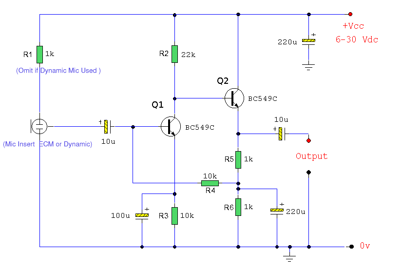
ECM Mic Preamplifier
Both transistors should be low-noise types. In the original circuit, BC650C was used, which is an ultra-low noise device. These transistors are now difficult to find, but BC549C or BC109C are good replacements. The circuit is self-stabilizing and will set...
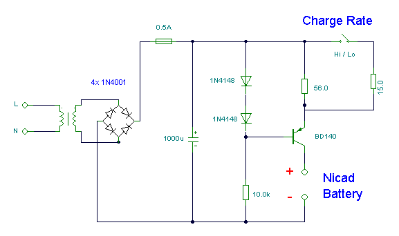
Nicad Battery Charger
This simple charger utilizes a single transistor as a constant current source. The voltage across a pair of 1N4148 diodes biases the base of the BD140 medium power transistor. The base-emitter voltage of the transistor and the forward voltage drop...
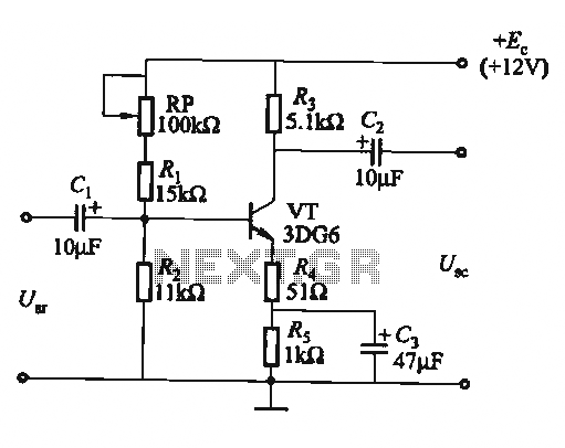
Transistor common emitter amplifier circuit
The circuit is a bias circuit for automatic stabilizers that maintains a stable quiescent operating point with good thermal stability. It utilizes a three-pole tube with an NPN type transistor, characterized by a small Iceo. An adjustment potentiometer, RP, is...
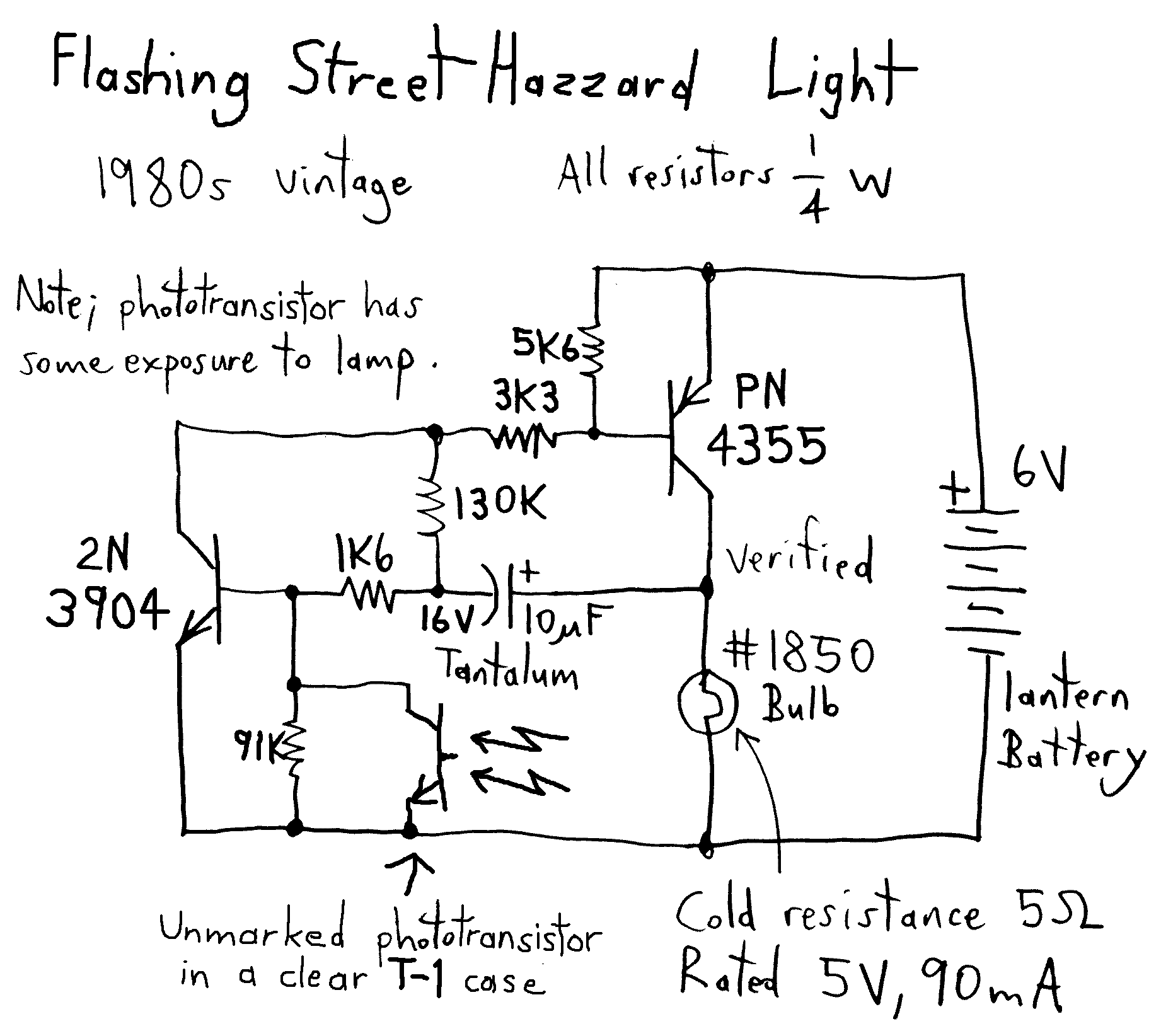
Toy Motor Drivers
This is a reverse-engineered circuit diagram of a one-transistor circuit commonly used to drive permanent magnet DC motors in children's toys. This circuit typically employs the 625mW version of the widely used 8050 or 8550 transistor. It is important to...
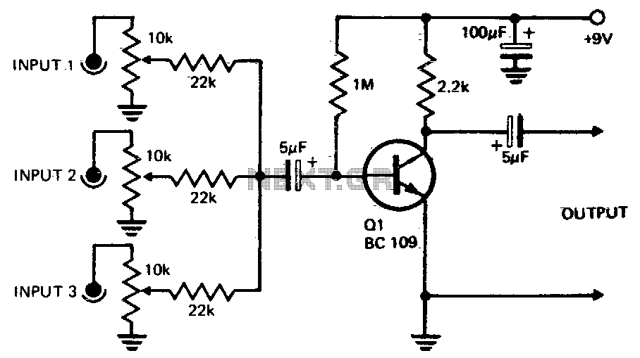
One transistor audio mixer
Three or more inputs with individual level controls feed into the base of Q1, which provides a voltage gain of 20.
The circuit design involves a transistor amplifier configuration where three or more input signals are managed through individual level control...