


Door-opener
#door-opener
#relay
#LASCR
#9V battery
#momentary-contact switch
#latching relay
#light source
#security
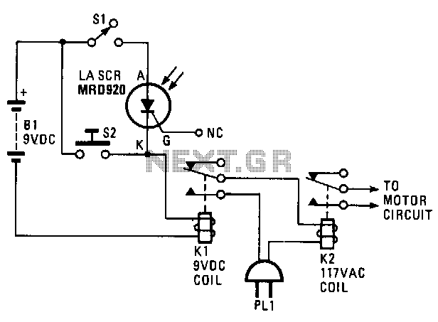
Description: The door opener is powered by a 9-V battery. A momentary-contact switch, labeled as 52, is included for manual opening and closing. Relay K1 is a 9-V type, while relay K2 is a latching type rated for 117 Vac, which automatically latches with the first burst of current and opens with the second burst. The gate lead of the LASCR is not utilized; instead, a light source activates the LASCR unit, allowing current to flow through the relay coil. This action causes the contacts of K1 to close, which energizes K2 (closing its contacts) and operates the garage door motor.
The door opener circuit is designed to facilitate the automatic operation of a garage door while also allowing for manual control. The power source, a 9-V battery, ensures that the system remains operational even during power outages. The momentary-contact switch (52) serves as a user interface, enabling the operator to manually engage or disengage the door opener as needed.
Relay K1, functioning at 9 V, acts as a primary control mechanism within the circuit. When the momentary-contact switch is activated, it energizes K1, closing its contacts. This action allows current to flow to relay K2, which is a latching relay rated for 117 Vac. The latching mechanism of K2 is critical; it remains in its last state (either open or closed) until the next pulse of current is applied. The first pulse energizes the relay, closing its contacts, while the second pulse de-energizes it, opening the contacts.
The LASCR (Light Activated Silicon Controlled Rectifier) plays a pivotal role in the circuit by responding to light signals. When the LASCR is triggered by a light source, it conducts, allowing current to flow through the coil of relay K1. This activation is essential for the operation of the door opener, as it ultimately leads to the energization of K2, which directly controls the garage door motor.
The overall design of this door opener circuit incorporates safety and convenience features, ensuring reliable operation while accommodating both automatic and manual controls. The integration of relays and the LASCR provides a robust solution for garage door automation, enhancing user experience and operational efficiency.The door opener derives its power from a 9-V battery. A momentary-contact switch, 52, is provided in the event that manual opening and closing is required. Relay Kl is a 9-V type and relay K2 is a 117"Vac latching-type, which automatically latches with the first burst of current and opens on the second burst.
The gate lead of the LASCR is not used; a light source triggers the LASCR unit into conduction, causing current to flow in the coil of the relay. That, in turn, causes Kl"s contacts to close, thereby energizing K2 (closing its contacts), and operating the garage door motor.
The door opener circuit is designed to facilitate the automatic operation of a garage door while also allowing for manual control. The power source, a 9-V battery, ensures that the system remains operational even during power outages. The momentary-contact switch (52) serves as a user interface, enabling the operator to manually engage or disengage the door opener as needed.
Relay K1, functioning at 9 V, acts as a primary control mechanism within the circuit. When the momentary-contact switch is activated, it energizes K1, closing its contacts. This action allows current to flow to relay K2, which is a latching relay rated for 117 Vac. The latching mechanism of K2 is critical; it remains in its last state (either open or closed) until the next pulse of current is applied. The first pulse energizes the relay, closing its contacts, while the second pulse de-energizes it, opening the contacts.
The LASCR (Light Activated Silicon Controlled Rectifier) plays a pivotal role in the circuit by responding to light signals. When the LASCR is triggered by a light source, it conducts, allowing current to flow through the coil of relay K1. This activation is essential for the operation of the door opener, as it ultimately leads to the energization of K2, which directly controls the garage door motor.
The overall design of this door opener circuit incorporates safety and convenience features, ensuring reliable operation while accommodating both automatic and manual controls. The integration of relays and the LASCR provides a robust solution for garage door automation, enhancing user experience and operational efficiency.The door opener derives its power from a 9-V battery. A momentary-contact switch, 52, is provided in the event that manual opening and closing is required. Relay Kl is a 9-V type and relay K2 is a 117"Vac latching-type, which automatically latches with the first burst of current and opens on the second burst.
The gate lead of the LASCR is not used; a light source triggers the LASCR unit into conduction, causing current to flow in the coil of the relay. That, in turn, causes Kl"s contacts to close, thereby energizing K2 (closing its contacts), and operating the garage door motor.
Isolated 24V Relay Controller
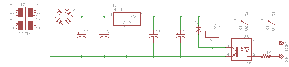
This is a common control voltage in industrial and telecommunications equipment, making relays frequently found in surplus equipment. Many relays can operate effectively on both AC and DC, providing a straightforward solution when the control voltage is switched mechanically, such...
DC relay circuits to delay the release of a second
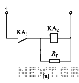
The circuit depicted in Figure 6-24 includes a relay coil with both ends connected in parallel to either a resistor Rf or an auxiliary diode VD. This configuration is equivalent to providing power after a short circuit, which increases the...
output relay delay audio amplifier
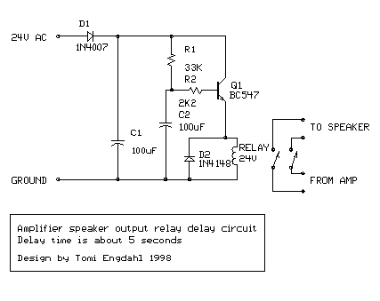
This is a simple circuit designed for an audio amplifier project to control the speaker output relay. The purpose of this circuit is to manage the delay that activates the relay, which connects the speakers to the audio amplifier. The...
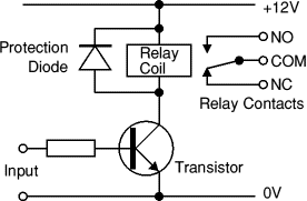
4 time ON-OFF relay circuit
A circuit is required where, upon power application, a timer triggers, keeping a relay in the off state. Once the timer completes its cycle, the relay will activate.
The circuit design consists of a timer integrated with a relay to control...
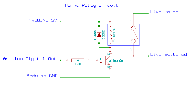
mains ac relay module
This mains AC relay module utilizes 5V relays that can be powered directly from an Arduino and can switch 230V. A basic energy monitoring and control system has been constructed using an Arduino 2009, off-the-shelf wireless remote control sockets, and...
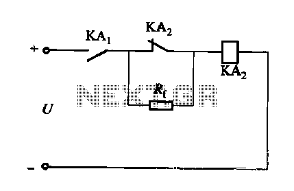
DC relay circuit to accelerate the release
A DC relay or contactor is utilized to enhance the excitation pull-in and release mechanisms in a circuit. The relay circuit, as depicted in Figure 6-28, facilitates improved return line efficiency. When the control relay KAi is activated, its normally...
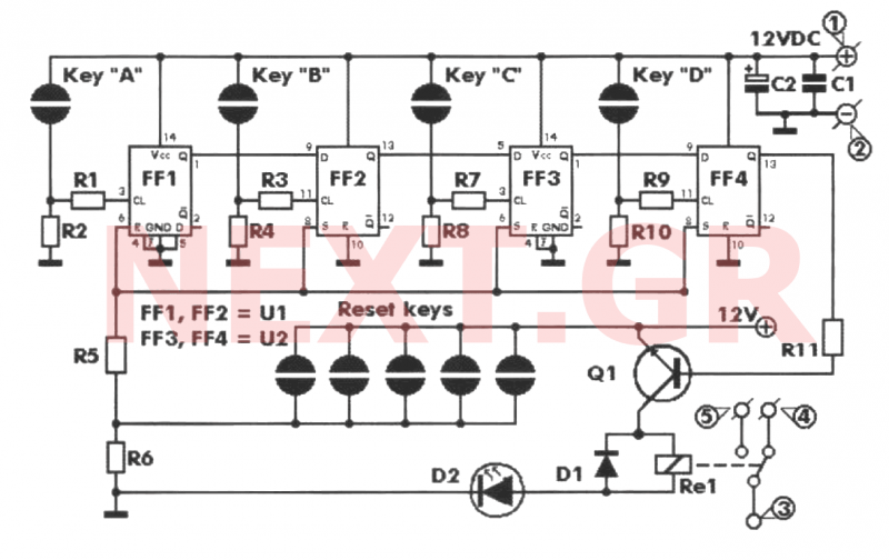
Key Code Combination High Security Door Lock
This project involves an electronic lock that supports numerous combinations, which can be easily modified. It unlocks only with the correct sequence of four consecutive numbers. A significant feature of this electronic lock is that the four numbers must be...
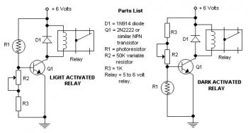
Dark and Light Activated Relay circuit diagram
The potentiometer adjusts the trigger level. The diode in the circuit diagram is specified as 1N914, which is suitable for light-duty relays; however, since the 1N914 is a signal diode, it is not ideal for this application. A 1N4001 diode...
chip programmer
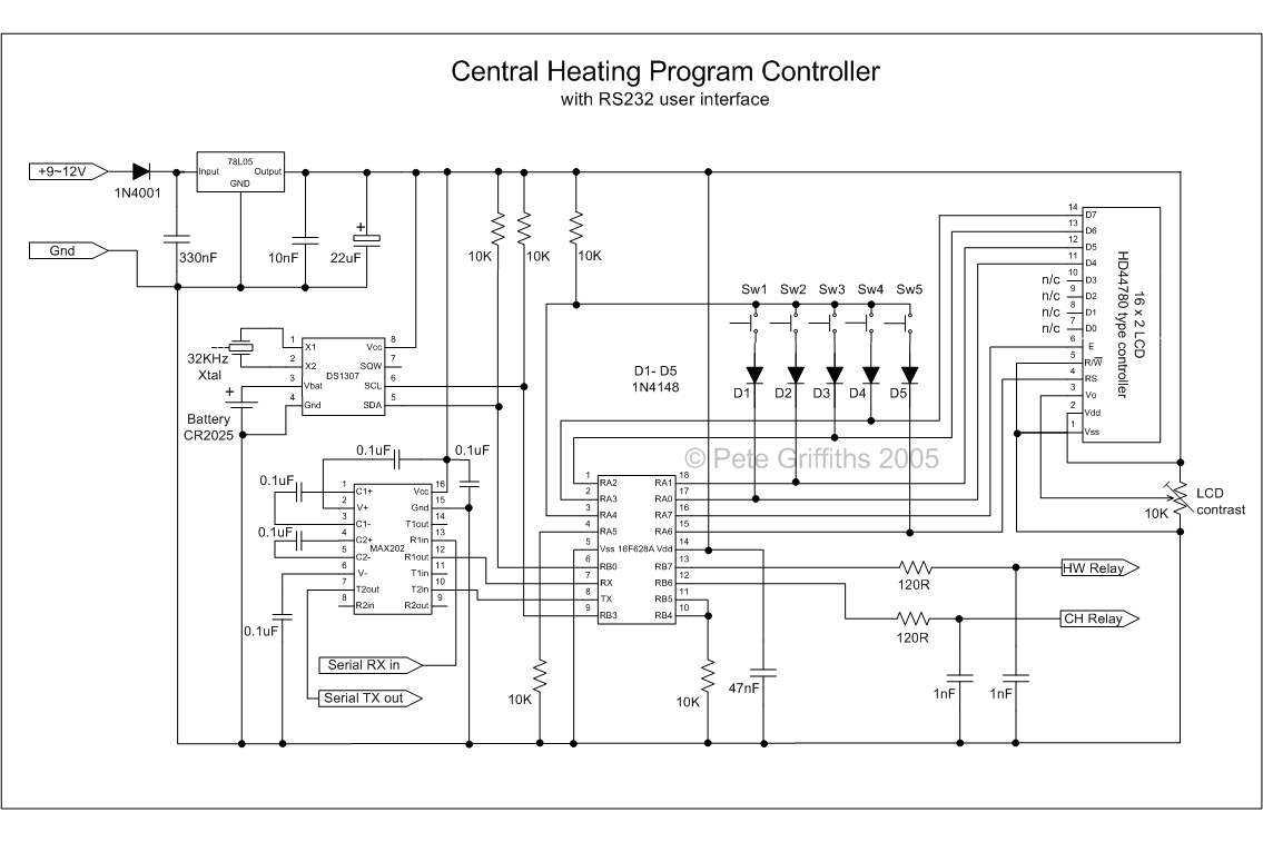
This project originated from the need to control home heating remotely from work. Utilizing a VPN connection between work and home, a relay controlled by a PC was considered the simplest solution. However, a control unit that could be operated...