


Doorknob touch alarm
#touch alarm
#flip-flop
#oscillator
#delay circuit
#audible alarm
#breadboard
#sensor
#dorm security
#educational
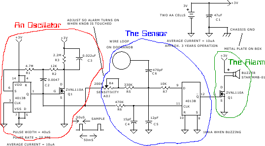
Description: The project was originally intended as a present for my brothers dorm room, but a bad capacitor and the lack of a proper oscilloscope caused delays. It has not made it off the breadboard, and it probably will not until his next semester. The circuit contains a few basic elements, a flip-flop based oscillator, a set of delays, a flip-flop as a sensor, and the audible alarm.
The described project incorporates several fundamental electronic components that work together to create a functional circuit. At the core of the design is a flip-flop based oscillator, which generates a square wave output. This oscillator can be implemented using various types of flip-flops, such as the 74HC74 dual D-type flip-flop or a 555 timer configured in astable mode. The output frequency of the oscillator can be adjusted by changing the resistor and capacitor values in the timing network.
The circuit also includes a set of delays, which can be achieved using additional flip-flops or dedicated delay circuits like the CD4040 binary counter or a 74HC123 monostable multivibrator. These delays can be used to control the timing of various events in the circuit, such as when the audible alarm should be activated or deactivated.
A second flip-flop serves as a sensor, which can be triggered by external stimuli, such as a button press or a change in voltage level. This flip-flop can be configured to toggle its output state based on the input signal, thereby allowing for the detection of specific events or conditions.
Finally, an audible alarm, typically a piezo buzzer or speaker, is integrated into the circuit to provide an audible indication of the circuit's status. The alarm can be connected to the output of the flip-flop sensor, ensuring that it activates when the sensor detects a change. The alarm's volume and tone can be influenced by the design of the driver circuit, which may include transistors or operational amplifiers to amplify the signal.
In summary, this circuit design combines a flip-flop based oscillator, delay circuits, a sensor flip-flop, and an audible alarm to create an interactive electronic project suitable for a dorm room environment. The use of breadboarding allows for easy modifications and troubleshooting before finalizing the design on a printed circuit board (PCB).The project was originally intended as a present for my brothers dorm room, but a bad capacitor and the lack of a proper oscilloscope caused delays. It has not made it off the breadboard, and it probably will not until his next semester. The circuit contains a few basic elements, an flip-flop based oscillator, a set of delays, a flip-flop as a sensor, and the audible alarm.
The described project incorporates several fundamental electronic components that work together to create a functional circuit. At the core of the design is a flip-flop based oscillator, which generates a square wave output. This oscillator can be implemented using various types of flip-flops, such as the 74HC74 dual D-type flip-flop or a 555 timer configured in astable mode. The output frequency of the oscillator can be adjusted by changing the resistor and capacitor values in the timing network.
The circuit also includes a set of delays, which can be achieved using additional flip-flops or dedicated delay circuits like the CD4040 binary counter or a 74HC123 monostable multivibrator. These delays can be used to control the timing of various events in the circuit, such as when the audible alarm should be activated or deactivated.
A second flip-flop serves as a sensor, which can be triggered by external stimuli, such as a button press or a change in voltage level. This flip-flop can be configured to toggle its output state based on the input signal, thereby allowing for the detection of specific events or conditions.
Finally, an audible alarm, typically a piezo buzzer or speaker, is integrated into the circuit to provide an audible indication of the circuit's status. The alarm can be connected to the output of the flip-flop sensor, ensuring that it activates when the sensor detects a change. The alarm's volume and tone can be influenced by the design of the driver circuit, which may include transistors or operational amplifiers to amplify the signal.
In summary, this circuit design combines a flip-flop based oscillator, delay circuits, a sensor flip-flop, and an audible alarm to create an interactive electronic project suitable for a dorm room environment. The use of breadboarding allows for easy modifications and troubleshooting before finalizing the design on a printed circuit board (PCB).The project was originally intended as a present for my brothers dorm room, but a bad capacitor and the lack of a proper oscilloscope caused delays. It has not made it off the breadboard, and it probably will not until his next semester. The circuit contains a few basic elements, an flip-flop based oscillator, a set of delays, a flip-flop as a sensor, and the audible alarm.
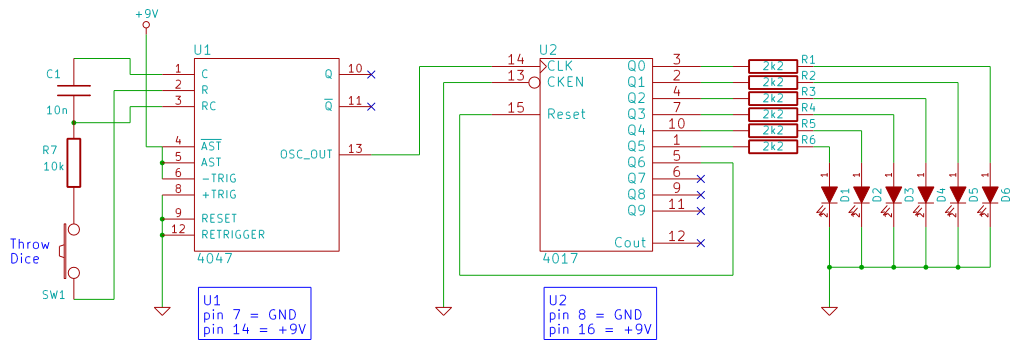
electronic dice
This beginner's breadboard circuit simulates the action of throwing a dice. By pressing a button, the circuit generates a random output, lighting up one of six LEDs to represent the result of the throw.
The circuit utilizes a microcontroller or a...

Variable Duty-Cycle Oscillator Circuit
A 1.2-kHz oscillator utilizing a potentiometer and steering diodes allows for a duty cycle adjustment ranging from 1% to 99%. The frequency can be altered by varying the capacitor CI. It is important to note that the diodes may slightly...

Half-duty-cycle-oscillator
The frequency of oscillation depends on the Rl/Cl time constant, allowing for frequency adjustment by varying Rl. This is a basic circuit.
The described circuit operates based on the relationship between resistance (Rl) and capacitance (Cl), which together form a time...

Electronic pests killing lamp circuit diagram 4
The electronic pest-killing lamp circuit comprises an oscillator, control circuit, high voltage generator, LED indicator circuit, and power supply circuit. The schematic diagram illustrates these components. The oscillator circuit includes a time-base integrated circuit (IC), resistors R5 to R7, diodes...

Sensor-Activated Relay Pulser Circuit
A sensor activates transistor Q1 to turn on the low-frequency 555 oscillator, which generates pulses to control LAMP II. The sensor may respond to variations in light or temperature. Either resistor RA or RB can function as the sensor, depending...
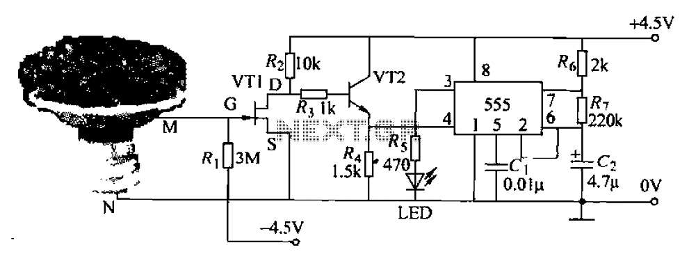
Pots water alarm circuit
The flowers in pots require watering, as relying solely on the observation of moist soil surfaces can be unreliable. To address this issue, a flower watering indicator has been developed. This circuit includes a field effect transistor (VT1), a second...
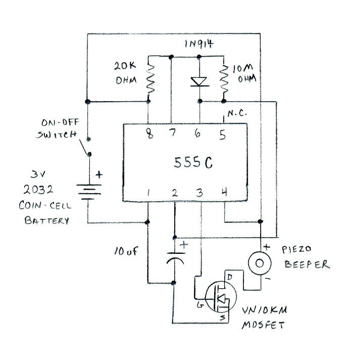
Nitty-gritty
The circuit diagram is shown below. It is recommended to lay out the circuit on a breadboard first to ensure functionality.
The circuit diagram refers to a schematic representation of an electronic circuit that outlines the components and their interconnections. To...
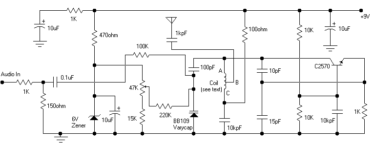
Colpitts oscillator FM transmitter
Its frequency depends on the capacitance of the vary cap diode. The center frequency is changed by varying the biasing voltage of the vary cap through the 47K pot. You can use a 75cm telescopic antenna or simply a length...
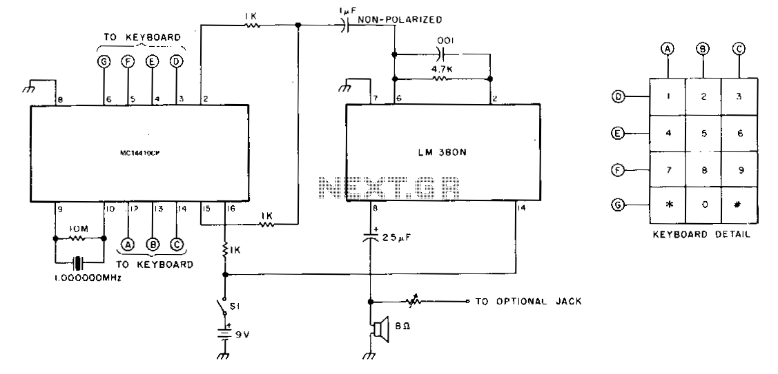
Simple-touchtonetm-generator
The oscillator utilizes a Motorola MC14410CP chip paired with a 1-MHz crystal. This configuration generates both high and low audio tones, which are then transmitted to the amplifier through 1 kΩ resistors and a 1 µF capacitor. The output resistors...