


Earth Fault Indicator
#earth fault
#mains voltage
#protective earth
#differential circuit breaker
#electrical safety
#fault detection
#security
#electrical devices
#PE connection
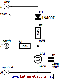
Description: The security of many electrical devices today relies on the availability of an earthed mains outlet. These outlets are connected to the frame or metal housing of the equipment, routing to the protective earth (PE) connections. In this configuration, any mains voltage, even if minimal, can cause the differential circuit breaker to trip. The circuit breaker is an essential component of modern electrical installations; however, it may become defective due to common corrosion, which has been observed in various older household devices and construction sites. These devices are often exposed to wet conditions, leading to gradual corrosion of the screw and/or lug used to connect the earth wire to the device frame, ultimately resulting in a break or faulty contact. The situation can be exacerbated as users, believing they are protected by the earth connection, may neglect special precautions, putting their safety at risk. A simple system to automatically detect any break in the earth connection is proposed, highlighting the need for such a feature in all factory-produced appliances that carry potential risks. The project involves a schematic where the live wire (L) of the mains power supply connects to diode D1, which facilitates basic half-wave rectification sufficient for the application. The current available is limited to a low value by resistor R2. If the appliance's earth connection is intact, the current is directed to earth through resistor R1, keeping the rest of the circuit inactive due to insufficient power. If the earth connection is severed, D1 and R2 supply current that charges capacitor C1. When the voltage across the capacitor reaches approximately 60 volts, neon indicator light La1 activates, emitting a flashing light while simultaneously discharging capacitor C1. This process continues indefinitely until the earth connection is restored, with the neon light serving as a warning signal in case of danger. While building the project is not overly complex, it is crucial to exercise maximum caution regarding component selection due to the safety implications. Capacitor C1 must have a minimum operating voltage of 160 volts, and R2 should be a 0.5-watt resistor, not for power dissipation but to maintain voltage levels. The neon light can be any type, potentially repurposed, or integrated into an indicator light for easier attachment to the protected appliance, in which case its series resistor should be removed to ensure proper functionality. During installation of the circuit in the appliance, clear markings for Live (L) and Neutral (N) should be made (e.g., using a simple screwdriver to identify Live), as reversing these wires will disable proper operation. It is essential to connect the earth connection for this setup to the frame of the appliance at a different point than where the normal earth wire is connected.
The proposed circuit serves as a safety mechanism that monitors the integrity of the earth connection in electrical appliances. The design utilizes a diode for rectification, ensuring that the circuit operates efficiently with minimal power requirements. The inclusion of a capacitor allows for the accumulation of voltage, which is critical for triggering the neon indicator. The neon light's flashing serves as a visual alert, indicating a potential safety hazard due to the disconnection of the earth wire.
When implementing this circuit, careful attention must be paid to the component ratings, particularly the voltage rating of the capacitor and the power rating of the resistor. These components must be chosen to withstand the operational conditions while ensuring long-term reliability. The design's simplicity is a significant advantage, as it can be easily integrated into existing appliances without extensive modifications.
Moreover, the installation process should emphasize safety and clarity in wiring connections to prevent accidental misconfiguration, which could lead to circuit failure or safety risks. This project highlights the importance of proactive safety measures in electrical engineering, particularly in environments where moisture and corrosion are prevalent. Overall, this circuit not only enhances the safety of electrical devices but also promotes awareness of the potential risks associated with faulty earth connections.The security of many electrical devices depends today on the availability of an earthed mains outlet. We should remember that these are connected to the frame or to the metal housing of the equipment and so it routes to the protective earth (PE) connections.
In this setup, mains voltage, however small, will cause the differential circuit breaker t o trip. The circuit breaker is part of any modern electrical installation. This type of security device may however become defective due to common corrosion as we have seen many times on various older household devices, as well as on construction sites. Actually, since these devices are frequently in wet conditions, the screw and/or lug used to connect the earth wire to the device frame corrodes gradually and ends up breaking or causing a faulty contact.
The remedy is then worse than the problem because the user, thinking that he/she is protected by earth, does not take special precautions and risks his/her life. However, all that`s needed is an extremely simple system to automatically detect any break in the earth connection; so simple that we ask ourselves why it is not already included as part of all factory production for appliances that carry any such risk, as we have discussed above.
We propose it as a project for you to build using this schematic. The live wire (L) of the mains power supply is connected to diode D1 which ensures simple half-wave rectification which is sufficient for our use. The current which is available is limited to a very low value by resistor R2. If the appliance earth connection to which our circuit is installed is efficient, this current is directed to earth via resistor R1 and the rest of the circuit is inactive due to insufficient power.
If the earth connection is disconnected, the current supplied by D1 and R2 charges up capacitor C1. When the voltage at the terminals of the capacitor reaches about 60 volts, neon indicator light La1 is turned on and emits a flashing light which discharges capacitor C1 at the same time. This phenomenon is reproduced indefinitely as long as the earth connection has not been restored, and the neon light continues to flash to attract attention in case of danger.
Building the project is not particularly difficult but, since it is a project aimed at human safety, we must take the maximum of precautions concerning the choice of components utilised. Therefore, C1 must have an operating voltage of at least 160 volts while R2 must be a 0. 5-watt resistor, not for reasons of power dissipation, but in order to maintain the voltage. The neon light can be any type, possibly used, or it may be part of an indicator light to make it easier to attach to the protected appliance.
In the second case, we must obviously get rid of its series resistor which would prevent proper operation here. During installation of the circuit in the appliance to be protected, we should also clearly mark Live (L) and Neutral (N) (for example, seek Live with a simple screwdriver) because inverting these two wires at this point will disable proper operation.
The final point, which is self-evident considering the principle used here: the earth connection for our setup must be hooked up to the frame of the appliance to be protected at a different point than where the normal earth wire is connected.
The proposed circuit serves as a safety mechanism that monitors the integrity of the earth connection in electrical appliances. The design utilizes a diode for rectification, ensuring that the circuit operates efficiently with minimal power requirements. The inclusion of a capacitor allows for the accumulation of voltage, which is critical for triggering the neon indicator. The neon light's flashing serves as a visual alert, indicating a potential safety hazard due to the disconnection of the earth wire.
When implementing this circuit, careful attention must be paid to the component ratings, particularly the voltage rating of the capacitor and the power rating of the resistor. These components must be chosen to withstand the operational conditions while ensuring long-term reliability. The design's simplicity is a significant advantage, as it can be easily integrated into existing appliances without extensive modifications.
Moreover, the installation process should emphasize safety and clarity in wiring connections to prevent accidental misconfiguration, which could lead to circuit failure or safety risks. This project highlights the importance of proactive safety measures in electrical engineering, particularly in environments where moisture and corrosion are prevalent. Overall, this circuit not only enhances the safety of electrical devices but also promotes awareness of the potential risks associated with faulty earth connections.The security of many electrical devices depends today on the availability of an earthed mains outlet. We should remember that these are connected to the frame or to the metal housing of the equipment and so it routes to the protective earth (PE) connections.
In this setup, mains voltage, however small, will cause the differential circuit breaker t o trip. The circuit breaker is part of any modern electrical installation. This type of security device may however become defective due to common corrosion as we have seen many times on various older household devices, as well as on construction sites. Actually, since these devices are frequently in wet conditions, the screw and/or lug used to connect the earth wire to the device frame corrodes gradually and ends up breaking or causing a faulty contact.
The remedy is then worse than the problem because the user, thinking that he/she is protected by earth, does not take special precautions and risks his/her life. However, all that`s needed is an extremely simple system to automatically detect any break in the earth connection; so simple that we ask ourselves why it is not already included as part of all factory production for appliances that carry any such risk, as we have discussed above.
We propose it as a project for you to build using this schematic. The live wire (L) of the mains power supply is connected to diode D1 which ensures simple half-wave rectification which is sufficient for our use. The current which is available is limited to a very low value by resistor R2. If the appliance earth connection to which our circuit is installed is efficient, this current is directed to earth via resistor R1 and the rest of the circuit is inactive due to insufficient power.
If the earth connection is disconnected, the current supplied by D1 and R2 charges up capacitor C1. When the voltage at the terminals of the capacitor reaches about 60 volts, neon indicator light La1 is turned on and emits a flashing light which discharges capacitor C1 at the same time. This phenomenon is reproduced indefinitely as long as the earth connection has not been restored, and the neon light continues to flash to attract attention in case of danger.
Building the project is not particularly difficult but, since it is a project aimed at human safety, we must take the maximum of precautions concerning the choice of components utilised. Therefore, C1 must have an operating voltage of at least 160 volts while R2 must be a 0. 5-watt resistor, not for reasons of power dissipation, but in order to maintain the voltage. The neon light can be any type, possibly used, or it may be part of an indicator light to make it easier to attach to the protected appliance.
In the second case, we must obviously get rid of its series resistor which would prevent proper operation here. During installation of the circuit in the appliance to be protected, we should also clearly mark Live (L) and Neutral (N) (for example, seek Live with a simple screwdriver) because inverting these two wires at this point will disable proper operation.
The final point, which is self-evident considering the principle used here: the earth connection for our setup must be hooked up to the frame of the appliance to be protected at a different point than where the normal earth wire is connected.

mains voltage monitor
Many electronics hobbyists have encountered the situation where a project is being completed late at night and the mains supply fails. The cause of the failure, whether due to the electricity provider or personal oversight, is not significant. In such...
Security Monitor
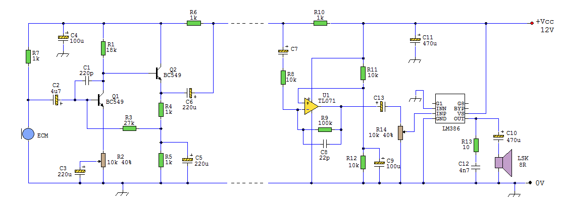
This circuit can be utilized in a garden setting to detect unusual sounds or wildlife noises. It can also monitor sounds around a car parked in a remote location. The cable used for the setup can either be visible or...

Key Code Combination High Security Door Lock
This project involves an electronic lock that supports numerous combinations, which can be easily modified. It unlocks only with the correct sequence of four consecutive numbers. A significant feature of this electronic lock is that the four numbers must be...
Security-door-ajar-alarm
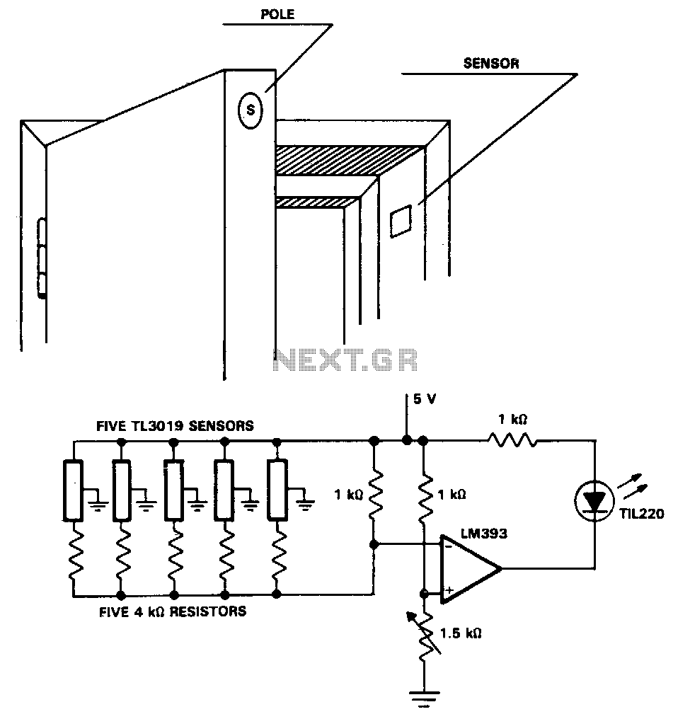
The TL3019 device activates, or goes low, when a south pole of a magnet approaches the chip face. In this example, there are five doors, each equipped with a magnet embedded in its edge, with the south pole facing outward....

Home Security System
This alarm circuit activates when switches S1 through S5 are engaged. This action illuminates LED1 and triggers transistor Q1 through integrated circuits IC1C and IC1D. Relay RY1 is configured for self-latching. Switch S10 is utilized for resetting the circuit. When...

mains voltage detector
The detector is designed to sense and signal to another circuit when an appliance is connected to the mains voltage. An optocoupler, identified as IC1 in the circuit, is utilized for this purpose. The light-emitting diode within the optocoupler is...

Mains Pulser Circuit
The pulser is designed to switch the mains voltage on and off at intervals ranging from just under one second to up to 10 minutes. This functionality is particularly useful for testing mains-operated equipment over extended periods or for the...

electronic hotel door vulnerability using stealth lock circuit
The term "pentester" refers to a penetration tester, individuals who assess security vulnerabilities. Many high-end hotels globally depend on keycard locks for securing hotel rooms. However, recent incidents of theft have shown that these locks may not be as secure...
Test wall socket with current limiting
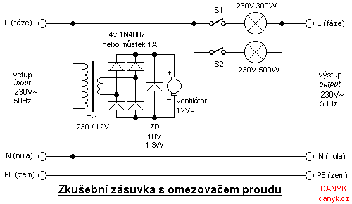
Individuals who frequently build, repair, and test equipment powered by mains voltage may encounter unexpected hazards, such as loud explosions, equipment destruction, flying components, tripped circuit breakers, and power outages. These incidents can be mitigated by utilizing a test wall...