


Economy radar detector circuit
#radar detector
#op-amp
#piezo transducer
#sensor circuit
#signal detection
#1458 dual op-amp
#current-to-voltage converter
#switching threshold
#security device
#automotive
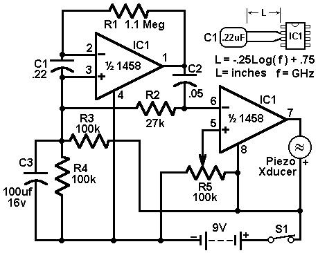
Description: This circuit utilizes a 1458 dual operational amplifier (op-amp) to create a radar detector. Capacitor C1 serves as the sensor for the radar signal. The first op-amp is configured as a current-to-voltage converter, while the second op-amp functions as a buffer to drive a piezo transducer. Resistor R5 establishes the switching threshold for the second op-amp, which is typically set to trigger just above the background noise level and then adjusted slightly lower. The circuit's response can be fine-tuned by modifying the length of the leads connected to C1. For standard road radar systems, the leads of the input capacitor should be approximately 0.5 to 0.6 inches in length.
This radar detector circuit employs a dual op-amp configuration, leveraging the 1458 device, which contains two independent, high-gain, frequency-compensated op-amps. The first op-amp is configured to convert the current generated by the radar signal detected by capacitor C1 into a corresponding voltage. This conversion is critical for effectively processing the weak radar signals that may be present in the environment.
The second op-amp acts as a buffer, ensuring that the output voltage from the first stage can drive the piezo transducer without being affected by load variations. This buffering stage is essential for maintaining signal integrity and ensuring that the transducer can produce a clear audible alert when radar signals are detected.
Resistor R5 plays a pivotal role in determining the sensitivity of the radar detection circuit. By setting the switching threshold, R5 allows the circuit to differentiate between actual radar signals and background noise. The ability to adjust this threshold is critical in environments where noise levels can vary significantly. The initial setting should be such that the circuit barely triggers on background noise, allowing for a more reliable detection of radar signals.
Furthermore, the performance of the circuit can be fine-tuned by adjusting the lead lengths of capacitor C1. The specified length of 0.5 to 0.6 inches is optimized for typical road radar systems, as this distance can affect the capacitance and, consequently, the sensitivity and response time of the detector. This adjustment allows for customization based on specific application requirements or environmental conditions.
In summary, this radar detector circuit exemplifies a straightforward yet effective design that utilizes a dual op-amp configuration to detect radar signals. The careful selection of component values and configurations ensures reliable operation, making it suitable for various radar detection applications.This circuit uses a 1458 dual op-amp to form a radar detector. C1 is the detector of the radar signal. The first op-amp forms a current-to-voltage converter and the second op-amp buffers the output to drive the piezo transducer. R5 sets the switching threshold of the second op-amp; normally it is adjusted so that the circuit barely triggers on bac
kground noise, then it`s backed off a bit. The response of the circuit may be tuned by adjusting the length of the leads on C1. For typical road-radar systems, the input capacitor`s leads should be about 0. 5 to 0. 6 inches long.
This radar detector circuit employs a dual op-amp configuration, leveraging the 1458 device, which contains two independent, high-gain, frequency-compensated op-amps. The first op-amp is configured to convert the current generated by the radar signal detected by capacitor C1 into a corresponding voltage. This conversion is critical for effectively processing the weak radar signals that may be present in the environment.
The second op-amp acts as a buffer, ensuring that the output voltage from the first stage can drive the piezo transducer without being affected by load variations. This buffering stage is essential for maintaining signal integrity and ensuring that the transducer can produce a clear audible alert when radar signals are detected.
Resistor R5 plays a pivotal role in determining the sensitivity of the radar detection circuit. By setting the switching threshold, R5 allows the circuit to differentiate between actual radar signals and background noise. The ability to adjust this threshold is critical in environments where noise levels can vary significantly. The initial setting should be such that the circuit barely triggers on background noise, allowing for a more reliable detection of radar signals.
Furthermore, the performance of the circuit can be fine-tuned by adjusting the lead lengths of capacitor C1. The specified length of 0.5 to 0.6 inches is optimized for typical road radar systems, as this distance can affect the capacitance and, consequently, the sensitivity and response time of the detector. This adjustment allows for customization based on specific application requirements or environmental conditions.
In summary, this radar detector circuit exemplifies a straightforward yet effective design that utilizes a dual op-amp configuration to detect radar signals. The careful selection of component values and configurations ensures reliable operation, making it suitable for various radar detection applications.This circuit uses a 1458 dual op-amp to form a radar detector. C1 is the detector of the radar signal. The first op-amp forms a current-to-voltage converter and the second op-amp buffers the output to drive the piezo transducer. R5 sets the switching threshold of the second op-amp; normally it is adjusted so that the circuit barely triggers on bac
kground noise, then it`s backed off a bit. The response of the circuit may be tuned by adjusting the length of the leads on C1. For typical road-radar systems, the input capacitor`s leads should be about 0. 5 to 0. 6 inches long.
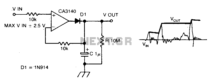
Precision peakvoltage detector
The circuit employs negative feedback exclusively for positive signals. The inverting input receives feedback only when diode D1 is forward biased, which occurs solely with positive input signals. As the positive input signal increases, the output of the operational amplifier...
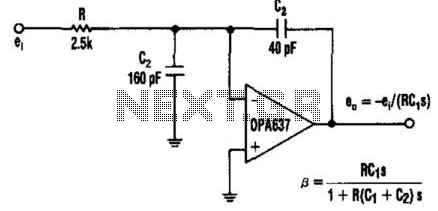
Capacitor Allows Higher Slew Rates
In this circuit, a Burr-Brown operational amplifier provides a slew rate of 135 V/μs. The inclusion of capacitor C2 reduces the high-frequency feedback factor to less than unity, enabling higher slew-rate amplifiers to be compensated for gains greater than one.
This...
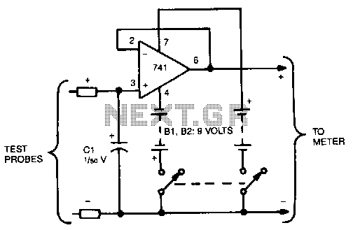
Voltage-freezer
This circuit reads and stores voltages, thereby freezing the meter reading even after the probes are removed. The operational amplifier (op-amp) is configured as a unity-gain voltage follower, with capacitor C1 located at the input to store the voltage. For...
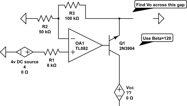
op amp Find Vo in an op-amp transistor circuit
The voltage measured at 12V after the emitter is perplexing, especially when the output from the op-amp is +15V, suggesting a 3V drop across the transistor. This raises questions about the expected gain of 2, which would imply an output...

Voltage Regulator For Cars And Motorcycles
This regulator circuit can be used on an alternator that has one field terminal grounded. When the input voltage becomes too high, Q1 conducts, and the base of Q2 is driven toward ground, reducing the voltage fed to Q3. This...
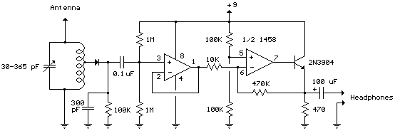
Simple Op-Amp Radio
The following schematic illustrates the Simple Op-Amp Radio Circuit Diagram sourced from bowdenshobbycircuits.info. This Simple Op-Amp Radio essentially functions as a crystal radio.
The Simple Op-Amp Radio Circuit utilizes an operational amplifier (op-amp) to enhance the performance of a basic crystal...
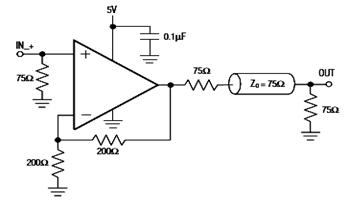
IC4030-4031 Typical Operating Circuit Schematic and Datasheet
The diagram below illustrates a typical operating circuit for the video line driver using the IC4030/4031 schematic. It incorporates the MAX4030E/MAX4031E, which are unity-gain stable operational amplifiers that offer high-speed performance, rail-to-rail outputs, and 15kV ESD protection, as stated in...
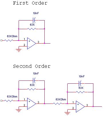
Audio Circuit(BassMidTreble)
The circuit design involves a circular operational amplifier (op-amp) configuration that functions as a second-order low-pass and high-pass filter. The low-pass filter operates within a frequency range of 20 to 250 Hz, while details regarding the high-pass filter are not...
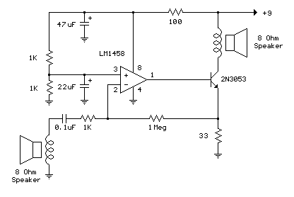
Low Power Op-Amp - Audio Amp (50 milliwatt) circuit
The example below illustrates the use of an operational amplifier (op-amp) as an audio amplifier in a basic intercom system. A small 8-ohm speaker is utilized as a microphone, which is connected to the op-amp input through a 0.1 µF...