


Electric fence control circuit 5
#electric fence
#high-voltage
#trigger control
#alarm circuit
#protection circuit
#power supply
#rectifier
#transformer
#filter capacitor
#current-limiting
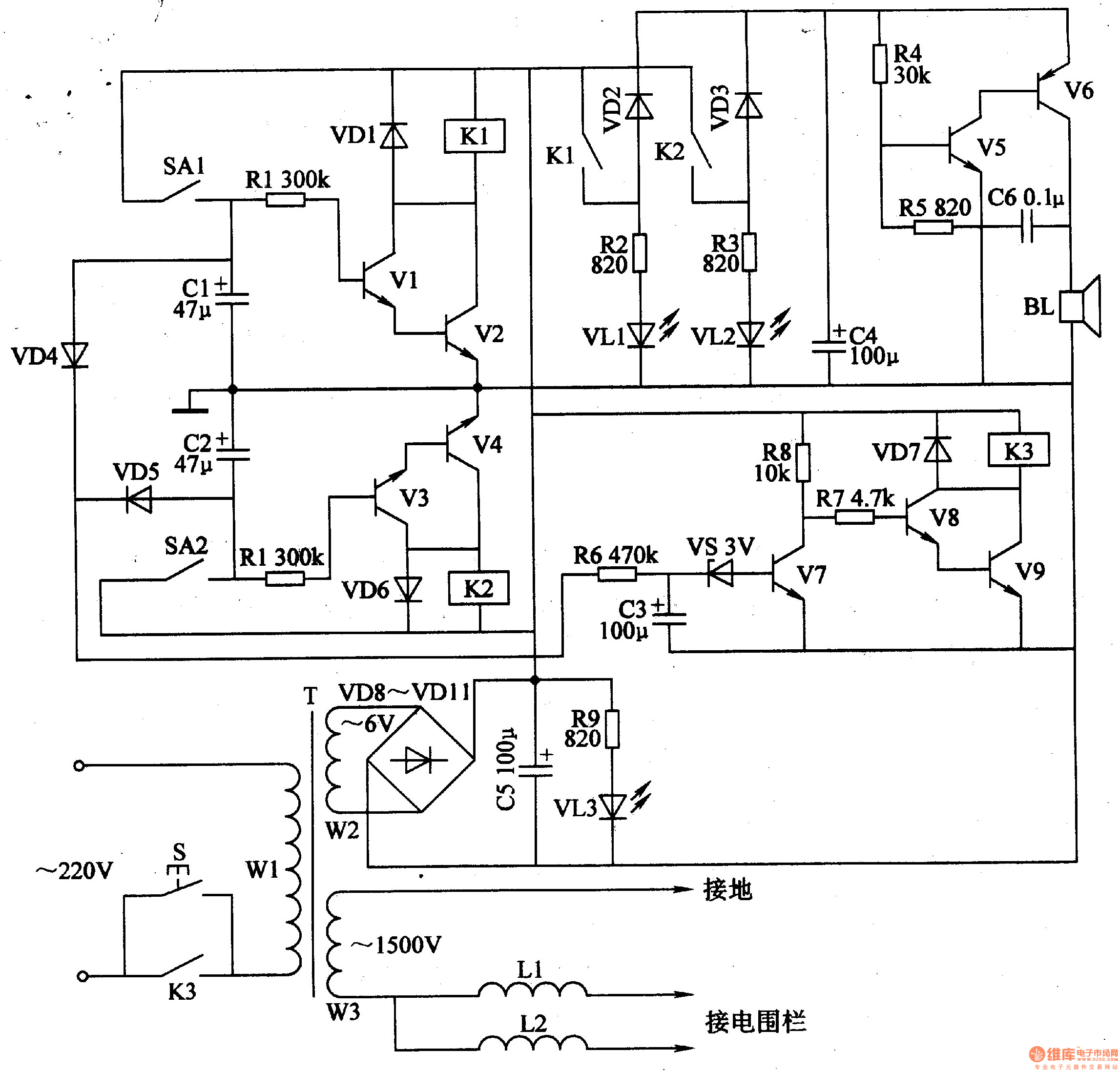
Description: The electric fence control circuit includes a +6 V power supply circuit, a high-voltage output circuit, a trigger control circuit, an alarm circuit, and a protection circuit. The +6 V power supply circuit consists of a power control button (S), a power transformer (T), rectifier diodes (VD8-VD11), a filter capacitor (C5), and a current-limiting component.
The electric fence control circuit operates by utilizing a +6 V power supply to facilitate the functioning of its various components. The power control button (S) serves as the primary switch, allowing the operator to turn the system on or off. The power transformer (T) steps down the voltage from the main supply to the required level, ensuring safe operation of the circuit.
Rectifier diodes (VD8-VD11) are employed to convert the alternating current (AC) output from the transformer into direct current (DC), which is essential for powering the circuit. The filter capacitor (C5) smooths out any ripples in the DC output, providing a stable voltage to the subsequent circuits.
The high-voltage output circuit generates the necessary voltage to create an electric charge along the fence line, deterring intruders. The trigger control circuit monitors the fence's integrity, activating the high-voltage output when a breach is detected. The alarm circuit provides audible or visual signals to alert the property owner of any unauthorized access attempts.
Finally, the protection circuit safeguards the entire system from overcurrent and voltage spikes, ensuring reliability and longevity of the electric fence control circuit. This comprehensive design ensures effective operation, safety, and ease of use for electric fencing applications.The electric fence control circuit is composed of the +6 V power supply circuit, high-voltage output circuit, trigger control circuit, alarm circuit and protection circuit, and it is shown in Figure 4-30. +6 V power supply circuit is composed of the power control button S, power transformer T, rectifier diodes VD8-VDll, filter capacitor C5, current-limiting..
The electric fence control circuit operates by utilizing a +6 V power supply to facilitate the functioning of its various components. The power control button (S) serves as the primary switch, allowing the operator to turn the system on or off. The power transformer (T) steps down the voltage from the main supply to the required level, ensuring safe operation of the circuit.
Rectifier diodes (VD8-VD11) are employed to convert the alternating current (AC) output from the transformer into direct current (DC), which is essential for powering the circuit. The filter capacitor (C5) smooths out any ripples in the DC output, providing a stable voltage to the subsequent circuits.
The high-voltage output circuit generates the necessary voltage to create an electric charge along the fence line, deterring intruders. The trigger control circuit monitors the fence's integrity, activating the high-voltage output when a breach is detected. The alarm circuit provides audible or visual signals to alert the property owner of any unauthorized access attempts.
Finally, the protection circuit safeguards the entire system from overcurrent and voltage spikes, ensuring reliability and longevity of the electric fence control circuit. This comprehensive design ensures effective operation, safety, and ease of use for electric fencing applications.The electric fence control circuit is composed of the +6 V power supply circuit, high-voltage output circuit, trigger control circuit, alarm circuit and protection circuit, and it is shown in Figure 4-30. +6 V power supply circuit is composed of the power control button S, power transformer T, rectifier diodes VD8-VDll, filter capacitor C5, current-limiting..
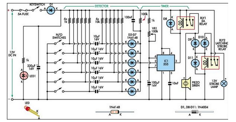
Simple 6-Input Alarm
This simple alarm circuit was designed for use in a combined garage and rumpus room. It can be assembled on Veroboard and uses just one IC plus a handful of additional components.
The alarm circuit is based on a single integrated...
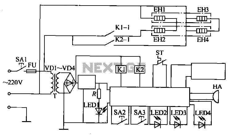
Electric oven circuit
The circuit operates by activating switch SA1, which powers a 220V transformer that converts AC voltage to DC through a bridge rectifier, supplying power to the computer control panel. The temperature for cooking food is set on this control panel,...
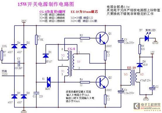
Structural analysis of switching power supply
A daily switching power supply primarily provides direct current (DC) power to electronic devices. The required DC voltage for electronic devices typically ranges from several volts to over ten volts, while the input voltage from the mains supply is either...
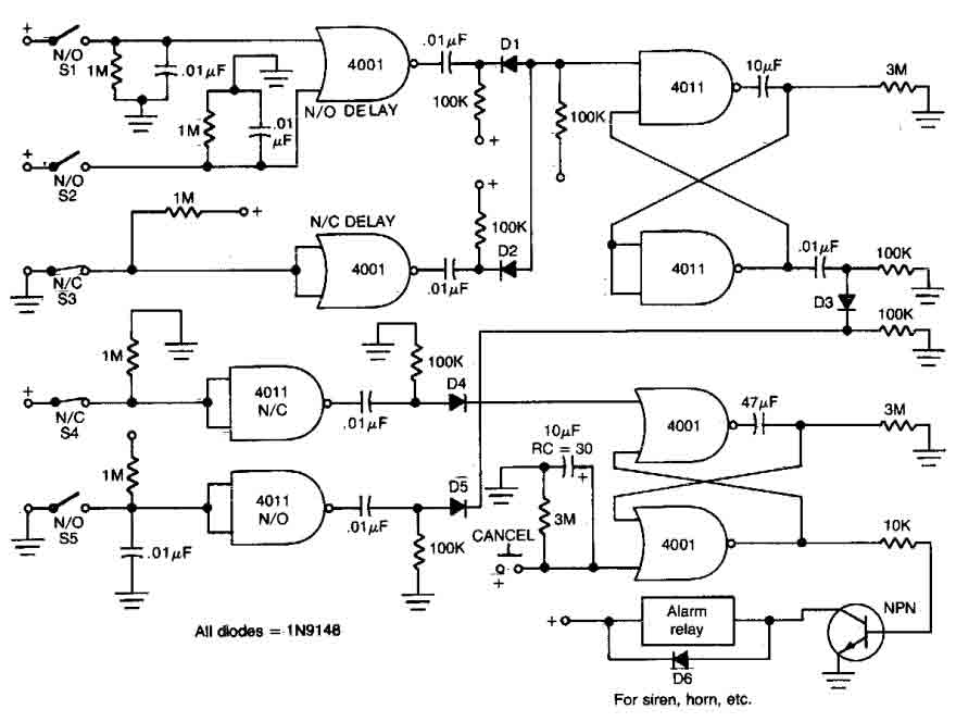
House Alarm Loop
This circuit features open and closed loop contacts (switches 1, 2, 3) that activate the alarm, which remains activated for 5 to 10 minutes. The triggering delay for entrance and exit is set to 27 seconds. Additionally, this simple alarm...
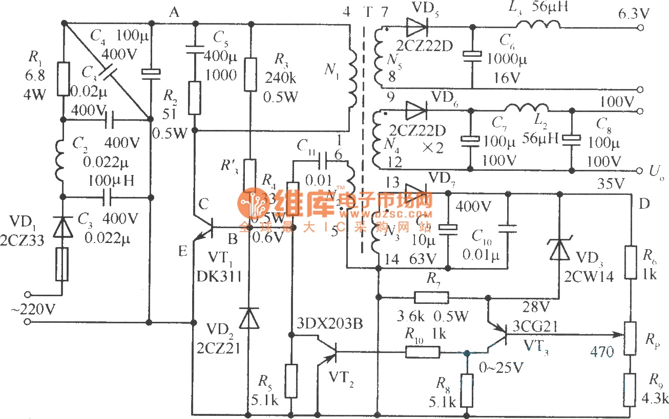
Output sampling winding isolated switching power supply
The diagram illustrates the output sampling winding of an isolated switching power supply. In the diagram, T represents a high-frequency transformer; N2 denotes the self-oscillation positive feedback winding; N3 is the error amplifier; VTS is the winding that provides the...
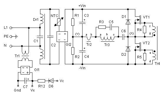
250 Watt PC power Supply
Up to 10 A continuous output current, or operation with 50 % ESD and 18 A peak current are possible without a fan if sufficient natural air flow is present and the ambient temperature does not exceed 30 °C. A...
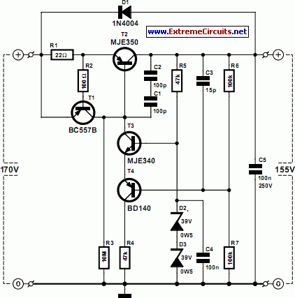
High-Voltage Regulator With Short Circuit Protection
There are many circuits for low voltage regulators. For higher voltages, such as supplies for valve circuits, the situation is different.
Low voltage regulators are widely utilized in electronic circuits to provide a stable output voltage from a varying input voltage...
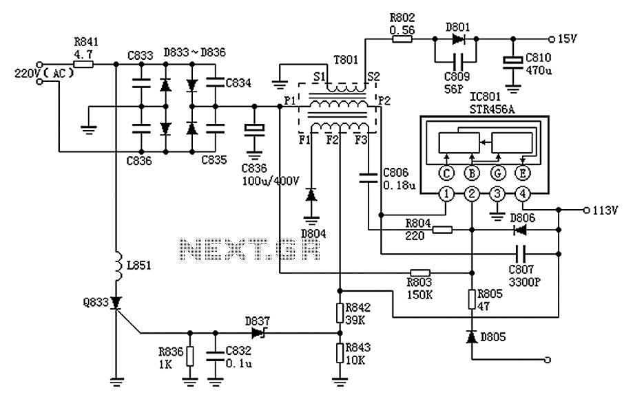
Panasonic M12H switching power supply circuit diagram
The Panasonic M12H switching power supply circuit is utilized in Panasonic models such as TC-230H, TC-2030DHN, TC-830D, and TC-840D. The circuit operates with an oscillation frequency that generates approximately 300V DC voltage at C836. The T801 transformer is involved in...
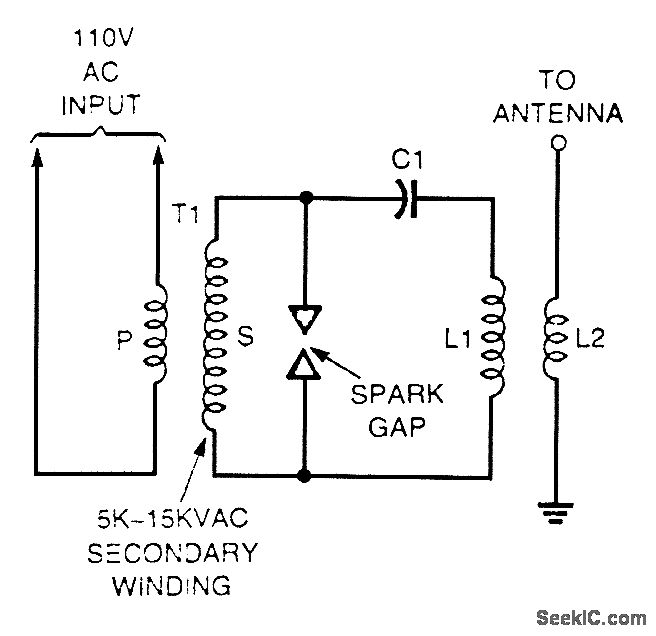
SPARK GAP OSCILLATOR
A high-voltage current-limiting transformer (T1) provides power to a basic LC tuned circuit. As capacitor C1 charges to approach the maximum output voltage of the transformer, the air gap in the spark gap breaks down, thereby completing the circuit between...