


Electronic Keys and Locks Circuits-Digital Code Locks-Combination and Transistor Code Locks
#electronic locks
#digital code locks
#transistor code locks
#combination locks
#security
#access control
#electronic keys
#circuit schematics
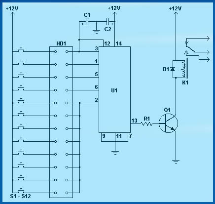
Description: Circuit diagram schematics of electronic keys, electronic locks, digital electronic locks, transistor code locks, and combination electronic locks.
The circuit schematics for electronic locking mechanisms encompass a variety of designs tailored to enhance security and convenience in access control systems.
1. **Electronic Keys and Locks**: These systems typically utilize a microcontroller to manage access permissions. An electronic key, often in the form of a key fob or card, communicates with the lock via RFID or infrared signals. The circuit includes a reader module that detects the key's signal, a microcontroller that processes the input, and a motor driver that actuates the locking mechanism.
2. **Digital Electronic Locks**: These locks employ a keypad interface where users input a numerical code to gain access. The schematic includes a keypad matrix, a microcontroller for code validation, and an actuator for the locking mechanism. Additional features may include an LCD display to provide user feedback and a buzzer for alert signals.
3. **Transistor Code Locks**: This type of lock uses transistors to control the locking mechanism based on a specific input code. The circuit design includes a series of switches or buttons connected to a transistor array, which activates the lock when the correct sequence is entered. The transistors serve as electronic switches, providing a robust method to control the power to the locking mechanism.
4. **Combination Electronic Locks**: These locks require a combination of inputs, often from both a keypad and a biometric sensor. The schematic integrates a microcontroller that processes multiple input types, ensuring enhanced security. The circuit may also feature a backup battery system to maintain functionality during power outages.
Overall, these electronic locking systems represent a convergence of various technologies, including microcontrollers, sensors, and actuators, to provide secure and efficient access control solutions. Each design can be customized based on specific security requirements and user preferences, making them versatile for residential and commercial applications.Circuit diagram schematics of Electronic Keys, Electronic Locks,Digital Electronic Locks,Transistor Code Locks,Combination Electronic Locks..
The circuit schematics for electronic locking mechanisms encompass a variety of designs tailored to enhance security and convenience in access control systems.
1. **Electronic Keys and Locks**: These systems typically utilize a microcontroller to manage access permissions. An electronic key, often in the form of a key fob or card, communicates with the lock via RFID or infrared signals. The circuit includes a reader module that detects the key's signal, a microcontroller that processes the input, and a motor driver that actuates the locking mechanism.
2. **Digital Electronic Locks**: These locks employ a keypad interface where users input a numerical code to gain access. The schematic includes a keypad matrix, a microcontroller for code validation, and an actuator for the locking mechanism. Additional features may include an LCD display to provide user feedback and a buzzer for alert signals.
3. **Transistor Code Locks**: This type of lock uses transistors to control the locking mechanism based on a specific input code. The circuit design includes a series of switches or buttons connected to a transistor array, which activates the lock when the correct sequence is entered. The transistors serve as electronic switches, providing a robust method to control the power to the locking mechanism.
4. **Combination Electronic Locks**: These locks require a combination of inputs, often from both a keypad and a biometric sensor. The schematic integrates a microcontroller that processes multiple input types, ensuring enhanced security. The circuit may also feature a backup battery system to maintain functionality during power outages.
Overall, these electronic locking systems represent a convergence of various technologies, including microcontrollers, sensors, and actuators, to provide secure and efficient access control solutions. Each design can be customized based on specific security requirements and user preferences, making them versatile for residential and commercial applications.Circuit diagram schematics of Electronic Keys, Electronic Locks,Digital Electronic Locks,Transistor Code Locks,Combination Electronic Locks..

electronic hotel door vulnerability using stealth lock circuit
The term "pentester" refers to a penetration tester, individuals who assess security vulnerabilities. Many high-end hotels globally depend on keycard locks for securing hotel rooms. However, recent incidents of theft have shown that these locks may not be as secure...
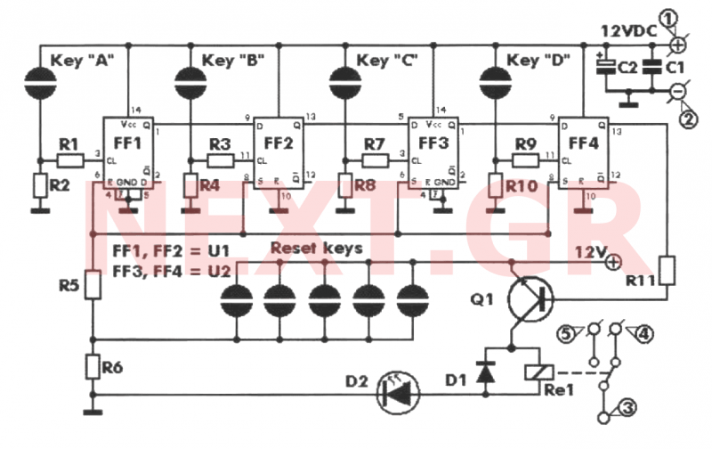
Key Code Combination High Security Door Lock
This project involves an electronic lock that supports numerous combinations, which can be easily modified. It unlocks only with the correct sequence of four consecutive numbers. A significant feature of this electronic lock is that the four numbers must be...
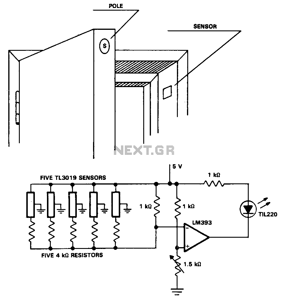
Security-door-ajar-alarm
The TL3019 device activates, or goes low, when a south pole of a magnet approaches the chip face. In this example, there are five doors, each equipped with a magnet embedded in its edge, with the south pole facing outward....
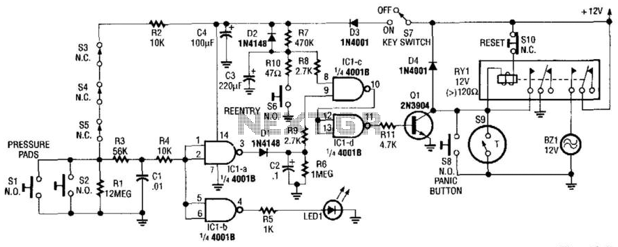
Home Security System
This alarm circuit activates when switches S1 through S5 are engaged. This action illuminates LED1 and triggers transistor Q1 through integrated circuits IC1C and IC1D. Relay RY1 is configured for self-latching. Switch S10 is utilized for resetting the circuit. When...
Locker Guard Locker Security Alarm Circuit Anti Theft
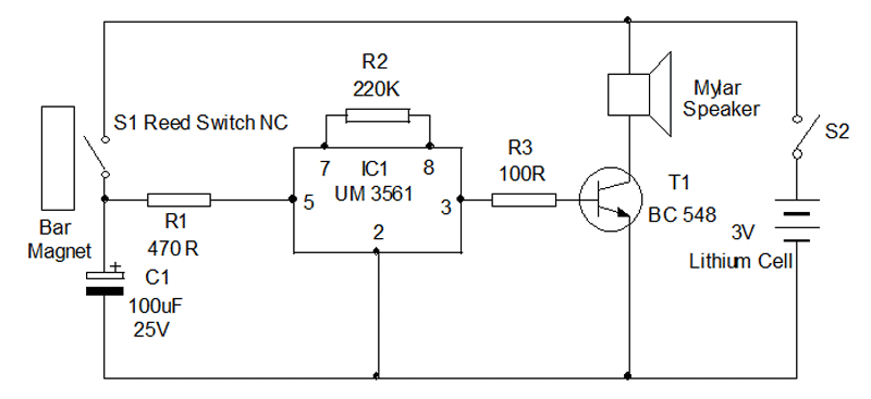
Locker Guard Circuit Diagram. This compact circuit is designed to protect a locker or almirah from burglary. If the locker is opened while in the armed state, the circuit triggers a loud police siren to deter the burglary attempt.
The Locker...

Midnight Security Light Circuit Schematic
Most thefts occur after midnight when individuals enter the second phase of sleep known as 'paradoxical sleep.' Here is an energy-saving circuit that causes...
An energy-saving circuit designed for security applications can be particularly beneficial during the late-night hours when individuals...

Security alarm
This alarm features both open-loop and closed-loop detection systems along with an automatic alarm shutoff mechanism. It provides a 15-second delay for exit and entrance. Additionally, the alarm activation time can be adjusted from 1 to 15 minutes.
The alarm system...
Automotive electronic locks circuit
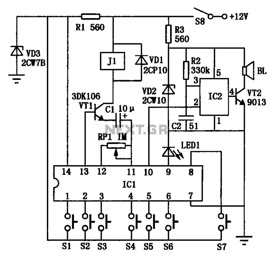
The automotive electronic locks circuit principle is illustrated with the dedicated lock IC 5G058. It features an external key switch connected to the positive power supply. The circuit includes six valid input keys, unlock keys S1 to S6, which must...
Electronic Locker Guard
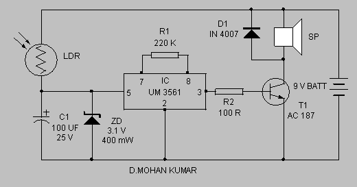
Protect your locker or briefcase from theft using this pocket-sized gadget. It emits a loud police siren to attract attention. The circuit utilizes a single integrated circuit (IC).
This circuit is designed to provide a compact and effective security solution for...