


Extra security for radio controlled alarms
#radio controlled
#security
#CMOS
#4093
#Schmitt trigger
#NAND gates
#servo
#transmitter signal
#astable multivibrator
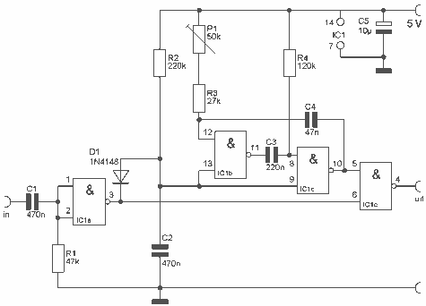
Description: This is a small circuit that provides extra security for radio controlled models. When the signal from the transmitter fails, grab the circuit and set the servo connected to a preset position. The circuit is built around a CMOS IC, the 4093 with 4 Schmitt trigger NAND gates. IC1b and IC1c together a astable multivibrator, which generates pulses for the servo. When a transmitter signal does not and this is the input signal is available at the output. More: With the servo position P1 can be set upon failure. The circuit is also used as a servo tester by the entrance not to join. R1 = 47 kOhm R2 = 220 kOhm R3 = 27 kOhm R4 = 120 kOhm P1 = 50 kOhm C1, C2 = 470 nF C3 = 220 nF C4 = 47 nF C5 = 10 uF D1 = 1N4148 IC1 = CMOS IC 4093
The described circuit serves as a fail-safe mechanism for radio-controlled models, ensuring that in the event of a signal loss from the transmitter, the servo is positioned to a predetermined location. The core of the circuit is the CMOS IC 4093, which contains four Schmitt trigger NAND gates. Specifically, gates IC1b and IC1c are configured as an astable multivibrator, generating a continuous pulse train that drives the servo motor.
The operation of the circuit begins with the transmitter sending a signal to the receiver. Under normal conditions, this signal is processed, allowing the servo to operate as intended. However, if the signal is interrupted, the circuit activates the astable multivibrator, which produces pulses that control the servo's position. The timing and frequency of these pulses can be adjusted based on the values of the resistors and capacitors used in the circuit.
The resistor values are as follows: R1 is 47 kΩ, R2 is 220 kΩ, R3 is 27 kΩ, and R4 is 120 kΩ. The potentiometer P1, with a value of 50 kΩ, allows for fine-tuning of the servo position in case of a signal failure. Capacitors C1 and C2 are both 470 nF, C3 is 220 nF, C4 is 47 nF, and C5 is 10 µF. The diode D1, a 1N4148, is included to protect the circuit from reverse polarity or voltage spikes.
Additionally, the circuit can function as a servo tester when the transmitter is not connected. This feature allows for testing the servo's operation independently, ensuring that the servo is functioning correctly before deployment in a model. Overall, this circuit design enhances the reliability of radio-controlled systems by providing a safeguard against signal loss, making it an essential component for hobbyists and professionals alike.This is a small circuit that provides extra security for radio controlled models. When the signal from the transmitter fails, grab the circuit and set the servo connected to a preset position. The circuit is built around a CMOS IC, the 4093 with 4 Schmitt trigger NAND gates. IC1b and IC1c together a astabiele multivibrator, which generates pulses for the servo. When a transmitter signal does not and this is the input signal is available at the output. With the servo position P1 can be set upon failure. The circuit is also used as a servo tester by the entrance not to join. R1 = 47 kOhm R2 = 220 kOhm R3 = 27 kOhm R4 = 120 kOhm P1 = 50 kOhm C1, C2 = 470 nF C3 = 220 nF C4 = 47 nF C5 = 10 uF D1 = 1N4148 IC1 = CMOS IC 4093
The described circuit serves as a fail-safe mechanism for radio-controlled models, ensuring that in the event of a signal loss from the transmitter, the servo is positioned to a predetermined location. The core of the circuit is the CMOS IC 4093, which contains four Schmitt trigger NAND gates. Specifically, gates IC1b and IC1c are configured as an astable multivibrator, generating a continuous pulse train that drives the servo motor.
The operation of the circuit begins with the transmitter sending a signal to the receiver. Under normal conditions, this signal is processed, allowing the servo to operate as intended. However, if the signal is interrupted, the circuit activates the astable multivibrator, which produces pulses that control the servo's position. The timing and frequency of these pulses can be adjusted based on the values of the resistors and capacitors used in the circuit.
The resistor values are as follows: R1 is 47 kΩ, R2 is 220 kΩ, R3 is 27 kΩ, and R4 is 120 kΩ. The potentiometer P1, with a value of 50 kΩ, allows for fine-tuning of the servo position in case of a signal failure. Capacitors C1 and C2 are both 470 nF, C3 is 220 nF, C4 is 47 nF, and C5 is 10 µF. The diode D1, a 1N4148, is included to protect the circuit from reverse polarity or voltage spikes.
Additionally, the circuit can function as a servo tester when the transmitter is not connected. This feature allows for testing the servo's operation independently, ensuring that the servo is functioning correctly before deployment in a model. Overall, this circuit design enhances the reliability of radio-controlled systems by providing a safeguard against signal loss, making it an essential component for hobbyists and professionals alike.This is a small circuit that provides extra security for radio controlled models. When the signal from the transmitter fails, grab the circuit and set the servo connected to a preset position. The circuit is built around a CMOS IC, the 4093 with 4 Schmitt trigger NAND gates. IC1b and IC1c together a astabiele multivibrator, which generates pulses for the servo. When a transmitter signal does not and this is the input signal is available at the output. With the servo position P1 can be set upon failure. The circuit is also used as a servo tester by the entrance not to join. R1 = 47 kOhm R2 = 220 kOhm R3 = 27 kOhm R4 = 120 kOhm P1 = 50 kOhm C1, C2 = 470 nF C3 = 220 nF C4 = 47 nF C5 = 10 uF D1 = 1N4148 IC1 = CMOS IC 4093
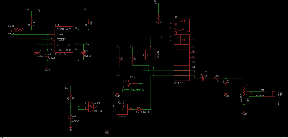
CMOS LFSR Vintage Atari Sound Effects Generator
Schematic for the CMOS Linear Feedback Shift Register Vintage Atari Sound Effects Generator circuit.
The circuit design consists of a CMOS Linear Feedback Shift Register (LFSR) that is utilized to generate sound effects reminiscent of vintage Atari games. The LFSR operates...
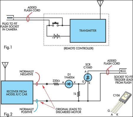
Radio Controlled Electronic Flash
A radio-controlled electronic flash is a valuable tool in any photographer's kit, frequently utilized by professionals. For instance, a wedding photographer may position one behind the bride to illuminate her gown and veil, avoiding visible wires in the shot. To...
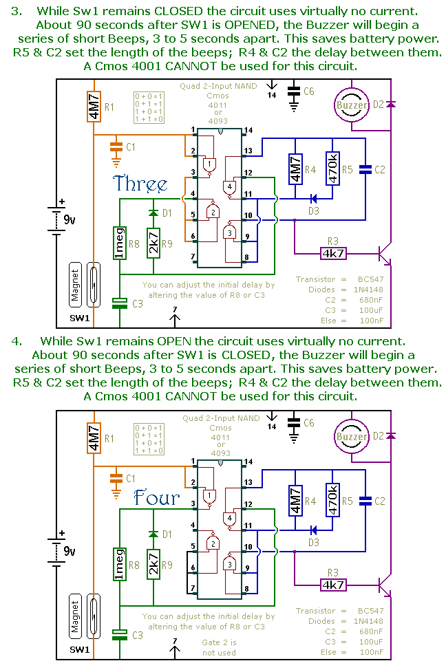
A Dozen Small Cmos Alarm Circuits circuit
This document presents a collection of compact, self-contained alarm circuits. These circuits are designed to operate with a very low standby current, making them ideal for battery-powered applications. They can be triggered by both normally-open and normally-closed switches, while some...
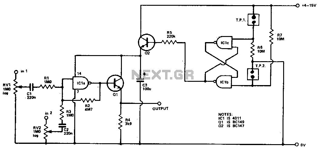
Cmos mixer
Four inputs can be mixed by duplicating the circuit to the left of C3 and using the fourth gate of ICI. Two gates are used in a touch-operated switching circuit that controls the voltage on the base of switching transistor...
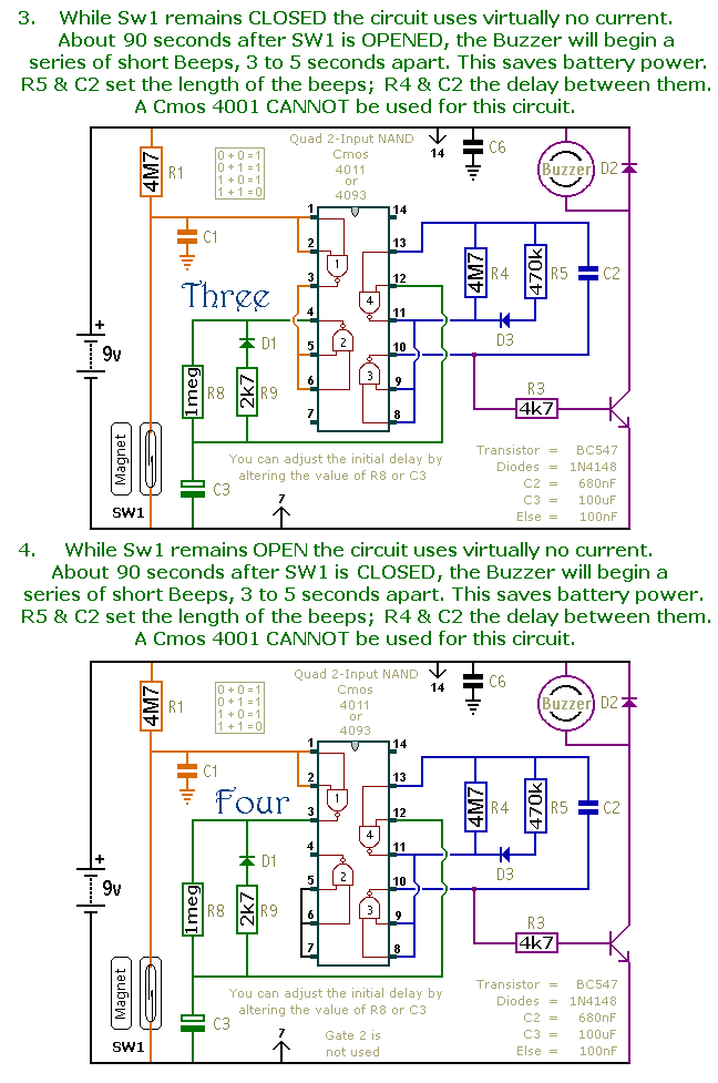
dozen small cmos alarm circuits
This is a collection of compact, self-sufficient alarm circuits designed for low standby current, making them ideal for battery operation. Some circuits are activated by normally-open and normally-closed switches, while others respond to variations in light or temperature. This leads...
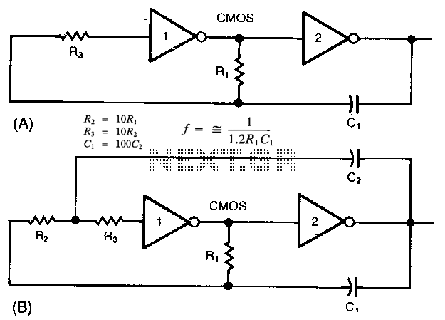
Cmos-oscillator
The common clock oscillator illustrated in Fig. 68-19A has two minor issues: it may not oscillate if the transition regions of its two gates differ. If it does oscillate, it might occasionally operate at a slightly lower frequency than predicted...
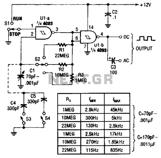
4093 Cmos Vfo Circuit
Two gates of a Quad 4093 are utilized in an astable multivibrator configuration. CI is a three-gang 365 pF variable capacitor with its sections connected in parallel. Additionally, S3 and S4 serve to switch in optional extra capacitors.
The described circuit...
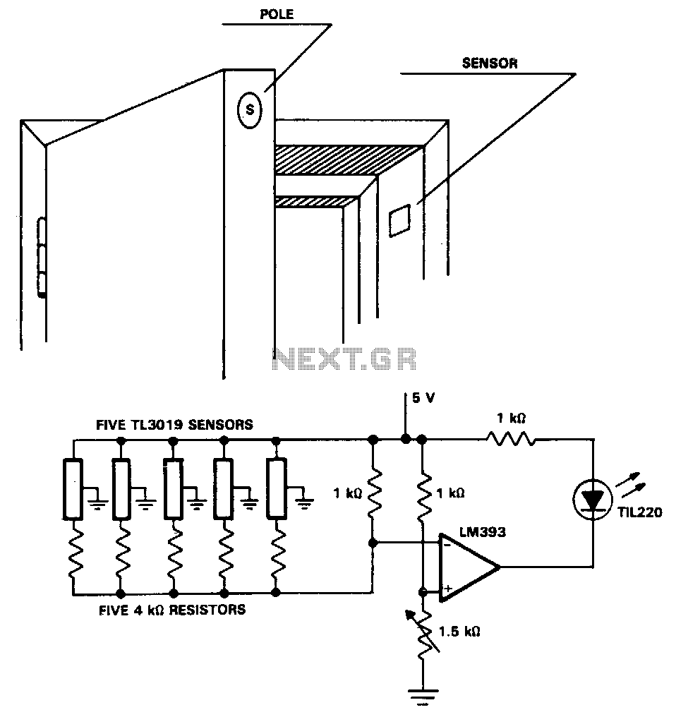
Security-door-ajar-alarm
The TL3019 device activates, or goes low, when a south pole of a magnet approaches the chip face. In this example, there are five doors, each equipped with a magnet embedded in its edge, with the south pole facing outward....

The SC (Schmitt Comparator) Head
I'll eventually post an explanation, but in the meantime, here it is. Meanwhile, a slightly refined version (with flashing LEDs to indicate "lock") was posted a few weeks later:
The provided description indicates a project involving a circuit that utilizes flashing...