


Flood-alarm-or-temperature-monitor
#thermistor
#transistor
#reed relay
#temperature monitoring
#alarm circuit
#sensor
#potentiometer
#switch

Description: A filtered 15 V DC supply is applied to a series circuit that includes a thermistor (R2) and a parallel combination of resistors (R1 and R3). The transistor (Q1) functions as a switch, with its state controlled by the setting of the potentiometer (R3). Initially, R3 is adjusted to allow just enough current to flow into the base of Q1 to turn it on when the thermistor is exposed to air. As the resistance of the thermistor decreases, the voltage at the base of Q1 increases. When the base current reaches the predetermined level, the transistor conducts, allowing current to flow through the reed relay coil, which closes the contacts of the reed relay. The base current of transistor Q1 is influenced by the environmental conditions surrounding the thermistor.
In this circuit, the thermistor R2 serves as a temperature sensor, responding to changes in its environment. When the temperature rises, the resistance of the thermistor decreases, leading to an increase in voltage at the base of the transistor Q1. The potentiometer R3 allows for fine-tuning of the base current, ensuring that the transistor operates within the desired threshold for activation.
The parallel resistors R1 and R3 create a voltage divider, which is essential for setting the correct base voltage for Q1. The configuration allows for flexibility in adjusting the sensitivity of the circuit to temperature changes. When the thermistor detects a temperature change, the corresponding change in resistance alters the voltage across R3, thereby influencing the base current of Q1.
The reed relay, which is activated by the current flowing through its coil when Q1 conducts, provides an effective means of controlling higher power loads with the low power signal from the transistor. This arrangement is particularly useful in applications where isolation between the control circuit and the load circuit is necessary.
Overall, this circuit exemplifies a simple yet effective method of using a thermistor in conjunction with a transistor switch and a relay to control devices based on temperature variations, demonstrating the principles of temperature sensing and electronic switching in practical applications.Filtered 15 V de is applied to a series circuit consisting of thermistor R2 and parallel combination of resistors Rl and R3. Transistor Ql acts as a switch whose state is determined by the setting of potentiometer R3, which is first set so just enough current flows into the base to switch on when the thermistor is in contact with air.
When the resistance of the thermistor decreases, the voltage at the base of Ql rises. When the base current reaches the preset level, the transistor conducts and passes current through the reed relay coil, closing the reed relay contacts. Current at the base of transistor Ql is determined by the environment into which the termistor is inserted.
In this circuit, the thermistor R2 serves as a temperature sensor, responding to changes in its environment. When the temperature rises, the resistance of the thermistor decreases, leading to an increase in voltage at the base of the transistor Q1. The potentiometer R3 allows for fine-tuning of the base current, ensuring that the transistor operates within the desired threshold for activation.
The parallel resistors R1 and R3 create a voltage divider, which is essential for setting the correct base voltage for Q1. The configuration allows for flexibility in adjusting the sensitivity of the circuit to temperature changes. When the thermistor detects a temperature change, the corresponding change in resistance alters the voltage across R3, thereby influencing the base current of Q1.
The reed relay, which is activated by the current flowing through its coil when Q1 conducts, provides an effective means of controlling higher power loads with the low power signal from the transistor. This arrangement is particularly useful in applications where isolation between the control circuit and the load circuit is necessary.
Overall, this circuit exemplifies a simple yet effective method of using a thermistor in conjunction with a transistor switch and a relay to control devices based on temperature variations, demonstrating the principles of temperature sensing and electronic switching in practical applications.Filtered 15 V de is applied to a series circuit consisting of thermistor R2 and parallel combination of resistors Rl and R3. Transistor Ql acts as a switch whose state is determined by the setting of potentiometer R3, which is first set so just enough current flows into the base to switch on when the thermistor is in contact with air.
When the resistance of the thermistor decreases, the voltage at the base of Ql rises. When the base current reaches the preset level, the transistor conducts and passes current through the reed relay coil, closing the reed relay contacts. Current at the base of transistor Ql is determined by the environment into which the termistor is inserted.
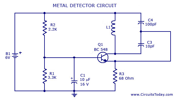
Metal Detector Circuit with Diagram and Schematic
A simple metal detector circuit diagram and schematic using a single transistor and a radio. This metal detector/sensor project is easy to make and is an application of a Colpitts oscillator.
The metal detector circuit utilizes a single transistor in conjunction...
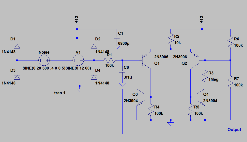
Transistor Clock
If you have been following on Twitter, you might have seen a tweet about a "Transistor Clock" kit that allows for the construction of a wall clock using 194 discrete transistors and numerous other components. This kit has been purchased,...
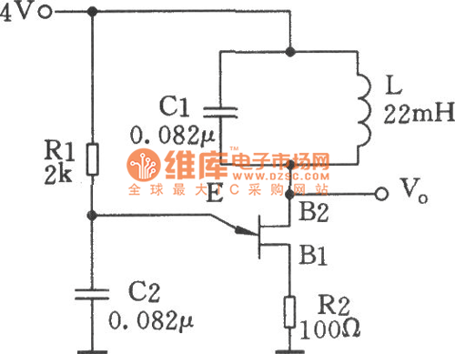
Single-junction transistor sine wave oscillator circuit
The single-junction transistor is commonly utilized in sawtooth and pulse generators, and it can also be configured to create a basic sine wave generation circuit. As an oscillator circuit composed of discrete components, it requires a minimal number of parts....
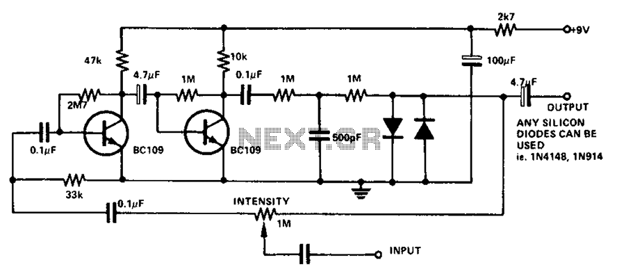
Boombox circuit diagram
The circuit utilizes a transistor to amplify the input signal. Two diodes are employed to clamp the distorted output, while a 500 pF capacitor filters out high-frequency noise. Under normal conditions, a 1M slide rheostat is used to adjust the...
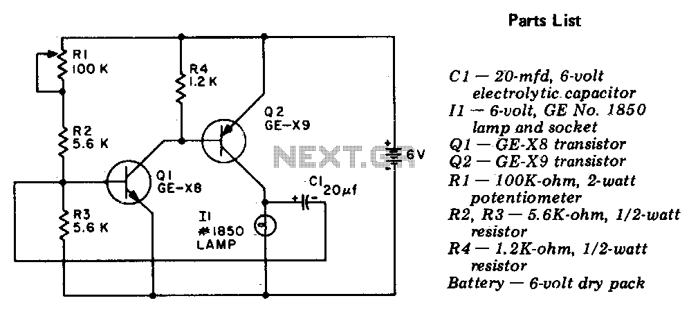
Flasher-light control
The circuit is a two-stage, direct-coupled transistor amplifier configured as a free-running multivibrator. Both the flash duration and flash interval can be adjusted by turning the potentiometer, R1.
The described circuit operates as a two-stage, direct-coupled transistor amplifier, functioning as a...
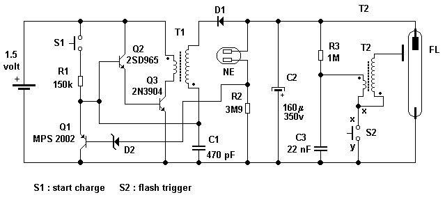
Camera flash circuit
A simple transistor generator and transformer converts a 1.5V battery voltage to several hundred volts. This high voltage current then passes through a diode, which rectifies the current to DC. This DC current is stored in a relatively large capacitor....
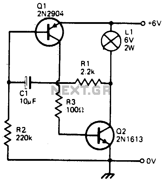
Transistorized flasher
This simple circuit will flash a 6-volt lamp at a rate determined by the size of capacitor C1. It is most economical on power as it only draws current when the lamp is on. When the lamp is off, both...
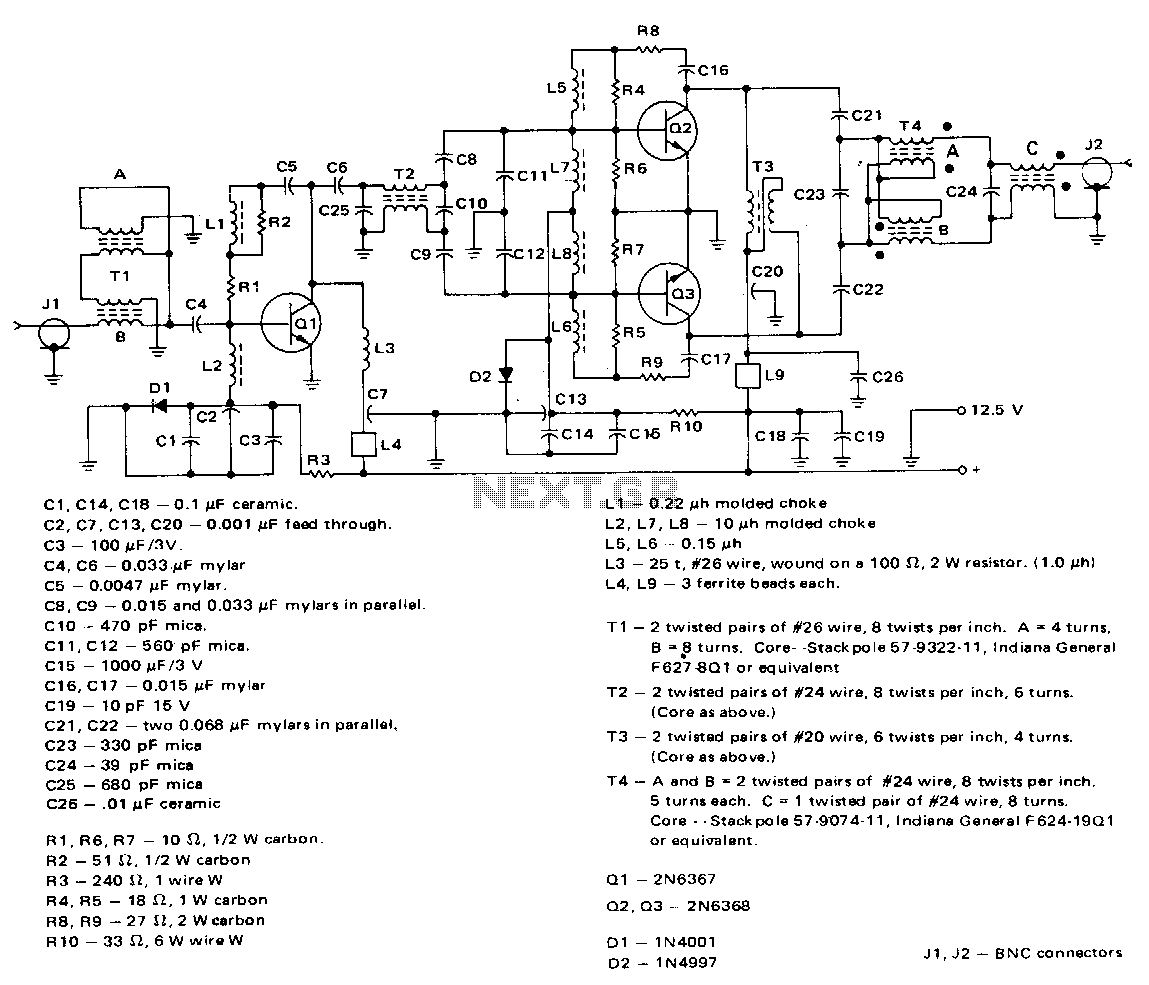
80W-3-30mhz-amplifier
This amplifier employs a 2N6367 transistor as a driver along with a pair of 2N6368 transistors. The 2N6367 is rated for a maximum output of 9 W (PEP) and is required to deliver 5 W (PEP) at 30 MHz, achieving...
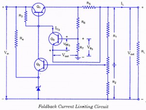
Controlled Transistor Series Regulator With Overload and Short-Circuit Protection
If the load resistance (RL) is reduced or the load terminals are accidentally shorted, a very large load current will flow, potentially damaging the pass transistor (Q1), diode, or other components. Fuse protection may not be sufficient, as the transistor...