


High-Low voltage cut-off with delay and alarm with circuit diagram
#voltage cut-off
#delay circuit
#alarm circuit
#protection circuit
#high voltage
#low voltage
#circuit diagram
#safety
#monitoring
#electronics
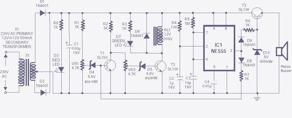
Description: The high and low voltage cut-off with delay and alarm circuit, along with its circuit diagram, is explained in this post.
The high and low voltage cut-off circuit is designed to protect electrical devices from damage caused by excessive voltage or insufficient voltage levels. This circuit operates by monitoring the input voltage and triggering a cut-off mechanism when the voltage exceeds or drops below predetermined thresholds. The inclusion of a delay feature ensures that transient voltage spikes do not inadvertently activate the cut-off, allowing the system to stabilize before making a decision. Additionally, an alarm system is integrated to alert users when the voltage levels are outside the acceptable range.
The circuit typically consists of a voltage sensing circuit, which can be implemented using operational amplifiers or comparators. These components continuously monitor the input voltage and compare it against reference voltage levels set by resistive voltage dividers. When the input voltage exceeds the upper threshold or falls below the lower threshold, the comparator output changes state.
A delay mechanism is often implemented using an RC (resistor-capacitor) network, which provides a time delay before the cut-off action is initiated. This delay prevents nuisance tripping due to brief voltage fluctuations. The output of the comparator can be connected to a relay or a MOSFET, which acts as the cut-off switch to disconnect the load from the power source.
For the alarm function, a simple buzzer or LED indicator can be employed. When the voltage is outside the specified range, the alarm circuit can be activated, providing a visual or audible indication to the user. The alarm system can be designed to remain active until the user manually resets it, ensuring that the user is aware of the voltage issue.
Overall, this circuit is essential in applications where voltage stability is critical, such as in power supplies for sensitive electronic equipment, ensuring both protection and user awareness of potential electrical issues.The high and low voltage cut-off with delay and alarm circuit with circuit diagram is explained in this post..
The high and low voltage cut-off circuit is designed to protect electrical devices from damage caused by excessive voltage or insufficient voltage levels. This circuit operates by monitoring the input voltage and triggering a cut-off mechanism when the voltage exceeds or drops below predetermined thresholds. The inclusion of a delay feature ensures that transient voltage spikes do not inadvertently activate the cut-off, allowing the system to stabilize before making a decision. Additionally, an alarm system is integrated to alert users when the voltage levels are outside the acceptable range.
The circuit typically consists of a voltage sensing circuit, which can be implemented using operational amplifiers or comparators. These components continuously monitor the input voltage and compare it against reference voltage levels set by resistive voltage dividers. When the input voltage exceeds the upper threshold or falls below the lower threshold, the comparator output changes state.
A delay mechanism is often implemented using an RC (resistor-capacitor) network, which provides a time delay before the cut-off action is initiated. This delay prevents nuisance tripping due to brief voltage fluctuations. The output of the comparator can be connected to a relay or a MOSFET, which acts as the cut-off switch to disconnect the load from the power source.
For the alarm function, a simple buzzer or LED indicator can be employed. When the voltage is outside the specified range, the alarm circuit can be activated, providing a visual or audible indication to the user. The alarm system can be designed to remain active until the user manually resets it, ensuring that the user is aware of the voltage issue.
Overall, this circuit is essential in applications where voltage stability is critical, such as in power supplies for sensitive electronic equipment, ensuring both protection and user awareness of potential electrical issues.The high and low voltage cut-off with delay and alarm circuit with circuit diagram is explained in this post..
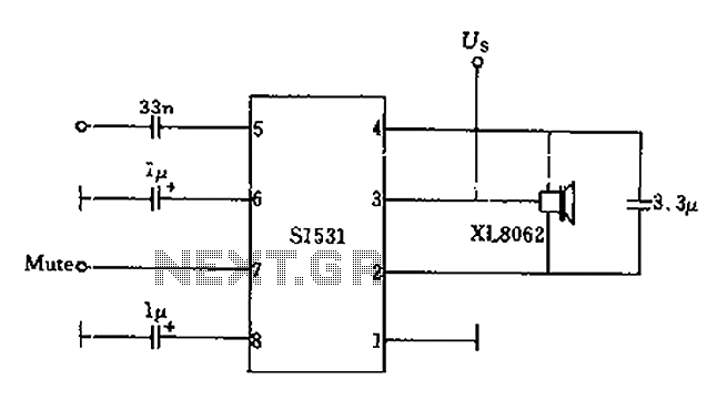
The battery voltage is low frequency amplifying circuit diagram 1v
The battery voltage is 1V for a low-frequency amplifying circuit, which can operate with a power supply voltage ranging from 1V to 1.7V, making it suitable for use with small batteries. The circuit provides an output power of 80mW with...
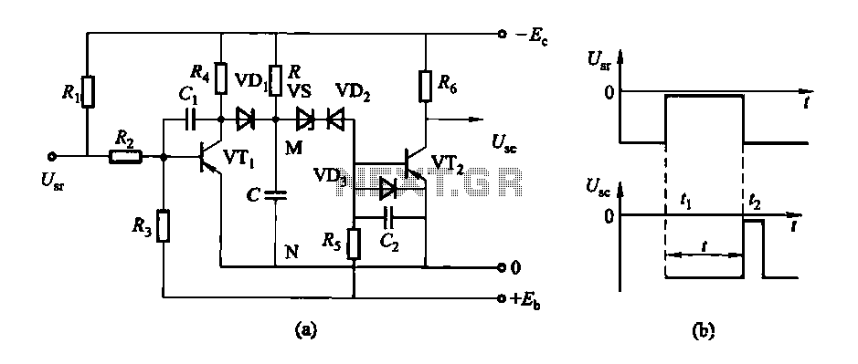
Conducting pipe control rechargeable delay circuit
The circuit features a delay action with an instantaneous reset control mechanism. It is categorized into three types: a conducting pipe rechargeable delay circuit, a tube cut-off control rechargeable delay circuit, and a discharge-type delay circuit. In the conducting pipe...
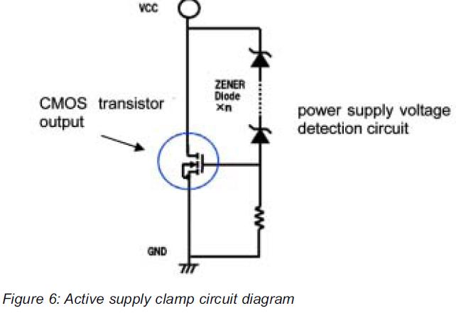
High Reliability for 1200V High Voltage Integrated Circuit for Half Bridge Applications
This article presents a high reliability 1200V High Voltage Integrated Circuit (1200V HVIC) for half bridge driver applications, aimed at reducing the IC's supply current by approximately 50%.
The 1200V High Voltage Integrated Circuit (HVIC) is designed specifically for half-bridge driver...
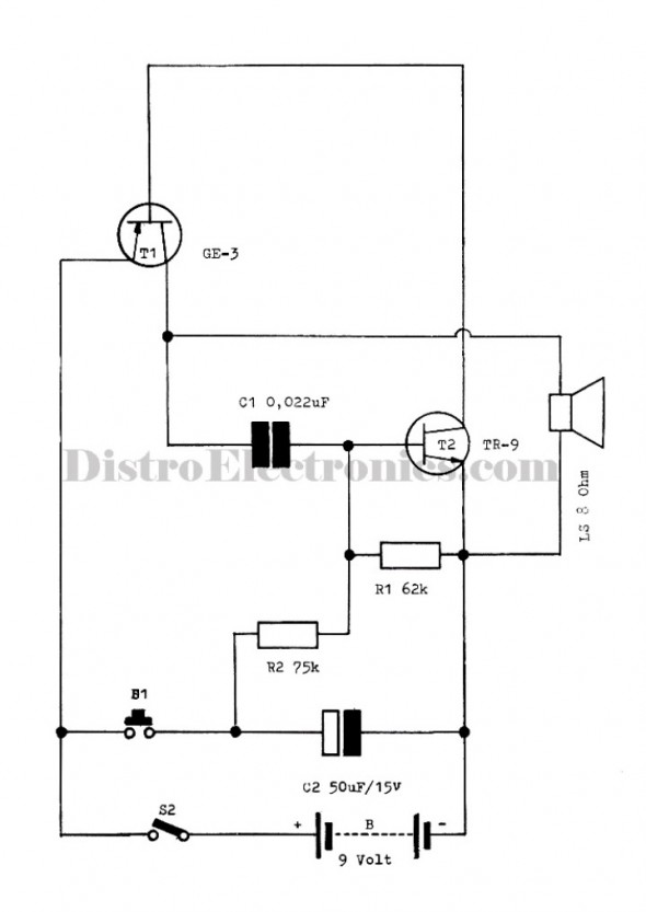
Easy Alarms Police / Ambulance Electronic
The following circuit illustrates the electronic diagram design for police and ambulance alarms. Features include simplicity and ease of assembly, as well as cost-effectiveness.
This electronic schematic represents a basic alarm system intended for use in police and ambulance applications. The...
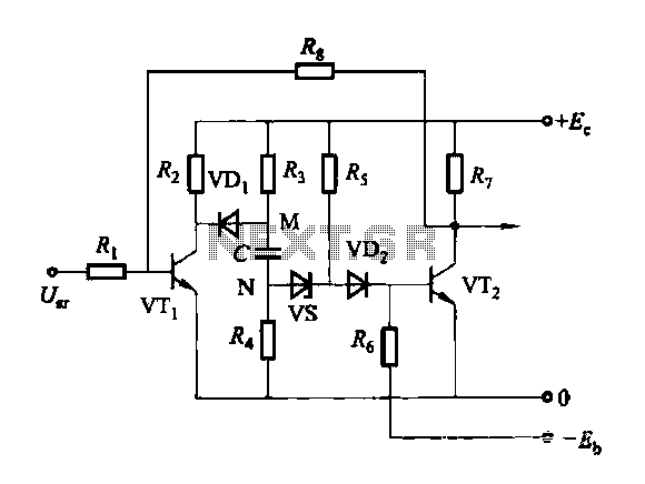
Discharge before memory circuit
Discharge before memory circuit. Before the memory circuit is activated, a delay reset circuit is required. When the input signal triggers an action, timing begins, and after a specified delay, the circuit reverts to its original state. During this interval,...
0 1000 volt regulated high voltage
The input voltage for the high-voltage DC-DC converter is 12V AC at 800mA, which is then converted to DC using a 1A bridge rectifier diode. The output voltage of the converter can be adjusted within the range of 0-1000V DC....
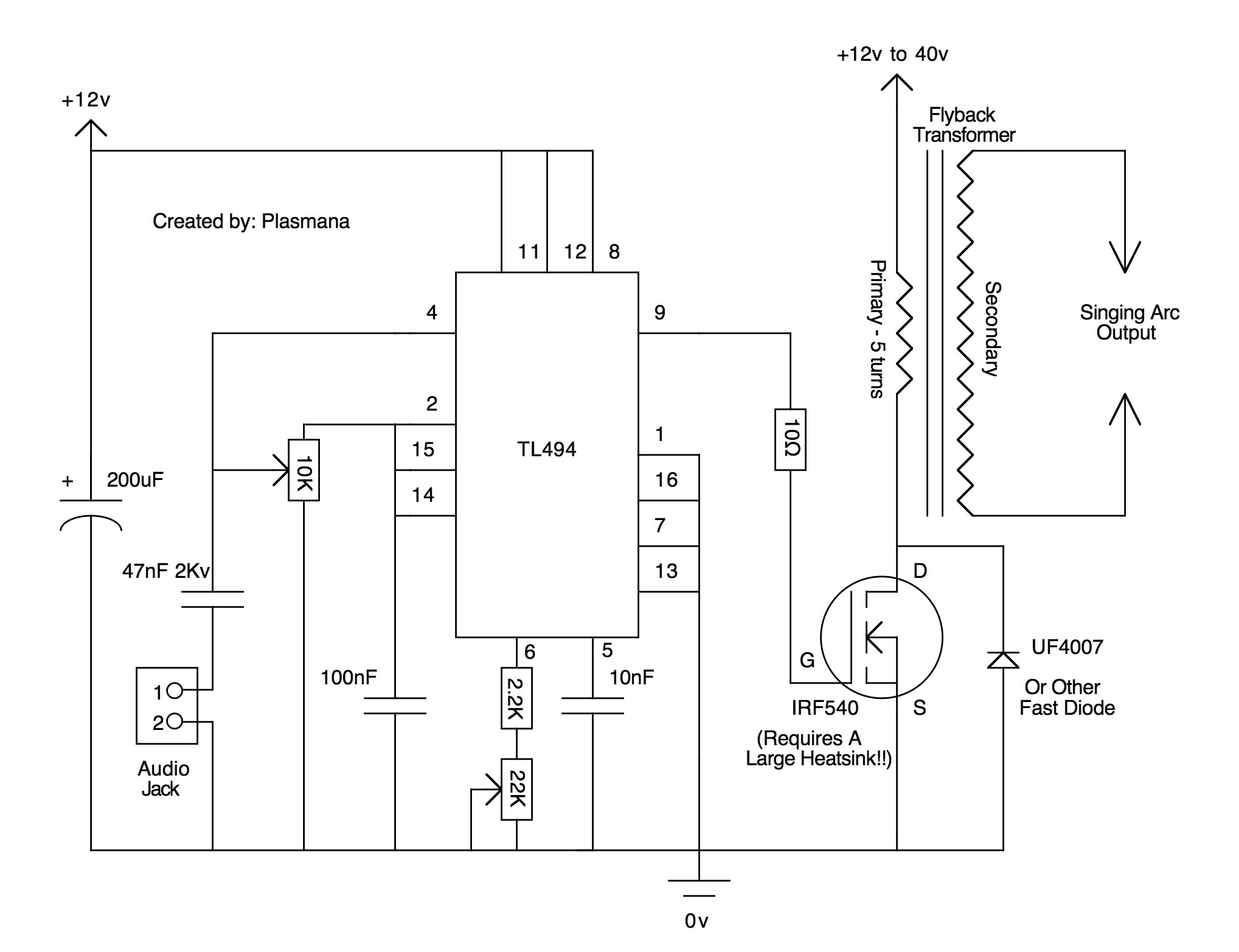
electricity
According to the datasheet, they will switch about 160 kW at up to 10 kV (7.2 kV typical). Unfortunately, this is insufficient for the quarter shrinker; however, a miniature ring flipper may be in development. A presentation will be held...
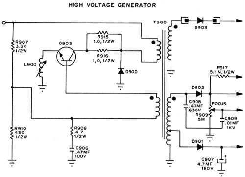
High Voltafe Generator
This is a series regulator with Q900 being the control element, Q901 a driver, and Q902 an error amp. ZD900 forms the emitter reference voltage source. Since the generated high voltage and other voltages are linked by means of the...
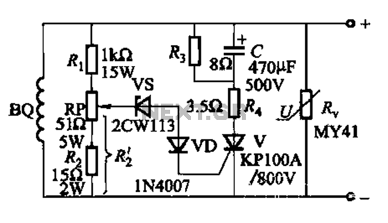
High voltage generator excitation set overvoltage protection circuit
The DC voltage for the generator field winding is supplied by a three-phase thyristor rectifier. In instances of incorrect operation, phase misalignment, or system failure, the rectifier may generate hazardous conditions, leading to over-voltage insulation issues on the DC side...