


High pressure alarm circuit
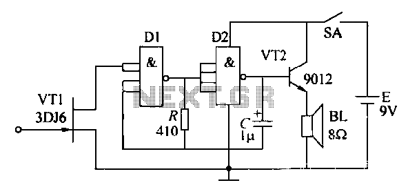
Description: High pressure alarm with high sensitivity. It detects high-voltage electric energy from 10kV at a distance of 2m or from low-voltage mains (AC 220V) at a distance of 0.3m. The alarm device is simple to manufacture, compact, and user-friendly. The schematic circuit for alarm 13120 is illustrated in the figure. The field effect transistor (VT1) operates when its gate is influenced by an electric field, which generates a gate bias due to the induced electric field. This results in an increase in the drain-source on-resistance, causing input D1 to register a high potential. The combination of diodes D1 and D2 forms an oscillator that generates an audio signal of approximately 1kHz, which is amplified by VT2 to drive a speaker for the alarm output. Diodes D1 and D2 utilize two sets of four-input NAND gates (74HC20 or 74LS20). The remaining components can be selected based on the reference model. The device can be installed in a portable radio cabinet, with the gate pad of VT1 connected to a 10cm long plastic soft wire extending outside the case, acting as an electric field sensor. After assembly, when positioned near the 220V AC power supply line, the speaker alarm operates correctly. To ensure safety, the alarm should be tested before being used near the 220V AC power supply line.
The high pressure alarm circuit is designed to provide an effective warning system for detecting high-voltage electric fields, ensuring safety in environments where high voltage is present. The core component, the field effect transistor (VT1), is sensitive to electric fields and is pivotal in the operation of the alarm. When the gate of VT1 is subjected to an electric field, it experiences a bias that alters its conductivity, thereby increasing the drain-source resistance. This change is critical as it allows the circuit to detect potential hazards from both high-voltage sources and low-voltage mains.
The oscillator circuit formed by diodes D1 and D2 generates a frequency of approximately 1kHz, which is suitable for audible alarms. The use of a 74HC20 or 74LS20 NAND gate IC for the oscillator provides reliability and ease of integration into the circuit. The amplified signal from VT2 drives a speaker, producing a loud alarm sound, alerting users to the presence of dangerous electrical fields.
The design emphasizes compactness and simplicity, making it suitable for various applications, including portable devices. The incorporation of a soft wire extending from the transistor's gate allows for flexible placement of the electric field sensor, enhancing detection capabilities. This feature is particularly beneficial in environments where high voltage lines are present, allowing for proactive safety measures.
For installation, the device should be housed in a sturdy enclosure, such as a portable radio cabinet, to protect the components while ensuring ease of use. It is essential to conduct thorough testing of the alarm functionality before deployment, particularly in proximity to high voltage AC power lines, to guarantee operational reliability and user safety. Proper calibration and positioning of the sensor will optimize the alarm's sensitivity and responsiveness, ensuring effective monitoring of high-voltage electric fields.High pressure alarm High sensitivity, high-voltage electric energy in the body from lOkV 2m at or away from the low-voltage mains (AC 220v) 0.3m at the alarm device yuan less device, the circuit is simple, easy to manufacture, small in size, easy to use. Schematic circuit alarm 13120 is shown in Fig. Field effect transistor is a field effect transistor VT1 device when its gate near the electric field due to the induced electric field generated gate bias. Drain-source on-resistance between the emergency will increase, corresponding inputs Dl showed a high potential by Dl, D2 vibration constituted oscillator start-up, resulting in approximately lkHz audio signal, the signal by VT2 amplified speaker sound an alarm input .
Dl, D2 using two sets of four-input NAND gate 74HC20 (74LS20). The remaining components of the reference model icon or parameter selection. The machine can be installed in the portable radio cabinet, on the VT1 gate pad section lOcm long plastic soft wire, extending outside the case for the electric field sensor chip used. After the assembly, which was close to the 220V AC power supply line, a speaker alarm sound is working properly, it can make use.
To ensure safety, the alarm fulfilled prior to use electricity, which is close to 2ZOV AC power supply line, such as the alarm can be used.
The high pressure alarm circuit is designed to provide an effective warning system for detecting high-voltage electric fields, ensuring safety in environments where high voltage is present. The core component, the field effect transistor (VT1), is sensitive to electric fields and is pivotal in the operation of the alarm. When the gate of VT1 is subjected to an electric field, it experiences a bias that alters its conductivity, thereby increasing the drain-source resistance. This change is critical as it allows the circuit to detect potential hazards from both high-voltage sources and low-voltage mains.
The oscillator circuit formed by diodes D1 and D2 generates a frequency of approximately 1kHz, which is suitable for audible alarms. The use of a 74HC20 or 74LS20 NAND gate IC for the oscillator provides reliability and ease of integration into the circuit. The amplified signal from VT2 drives a speaker, producing a loud alarm sound, alerting users to the presence of dangerous electrical fields.
The design emphasizes compactness and simplicity, making it suitable for various applications, including portable devices. The incorporation of a soft wire extending from the transistor's gate allows for flexible placement of the electric field sensor, enhancing detection capabilities. This feature is particularly beneficial in environments where high voltage lines are present, allowing for proactive safety measures.
For installation, the device should be housed in a sturdy enclosure, such as a portable radio cabinet, to protect the components while ensuring ease of use. It is essential to conduct thorough testing of the alarm functionality before deployment, particularly in proximity to high voltage AC power lines, to guarantee operational reliability and user safety. Proper calibration and positioning of the sensor will optimize the alarm's sensitivity and responsiveness, ensuring effective monitoring of high-voltage electric fields.High pressure alarm High sensitivity, high-voltage electric energy in the body from lOkV 2m at or away from the low-voltage mains (AC 220v) 0.3m at the alarm device yuan less device, the circuit is simple, easy to manufacture, small in size, easy to use. Schematic circuit alarm 13120 is shown in Fig. Field effect transistor is a field effect transistor VT1 device when its gate near the electric field due to the induced electric field generated gate bias. Drain-source on-resistance between the emergency will increase, corresponding inputs Dl showed a high potential by Dl, D2 vibration constituted oscillator start-up, resulting in approximately lkHz audio signal, the signal by VT2 amplified speaker sound an alarm input .
Dl, D2 using two sets of four-input NAND gate 74HC20 (74LS20). The remaining components of the reference model icon or parameter selection. The machine can be installed in the portable radio cabinet, on the VT1 gate pad section lOcm long plastic soft wire, extending outside the case for the electric field sensor chip used. After the assembly, which was close to the 220V AC power supply line, a speaker alarm sound is working properly, it can make use.
To ensure safety, the alarm fulfilled prior to use electricity, which is close to 2ZOV AC power supply line, such as the alarm can be used.
General-Purpose Alarm
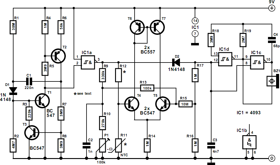
The alarm can be utilized for various applications, including frost monitoring and room temperature monitoring. In its quiescent state, the circuit consumes only a few microamperes, allowing a 9 V dry battery (PP3, 6AM6, MN1604, 6LR61) to potentially last up...
High-voltage isolation switch operation display circuit
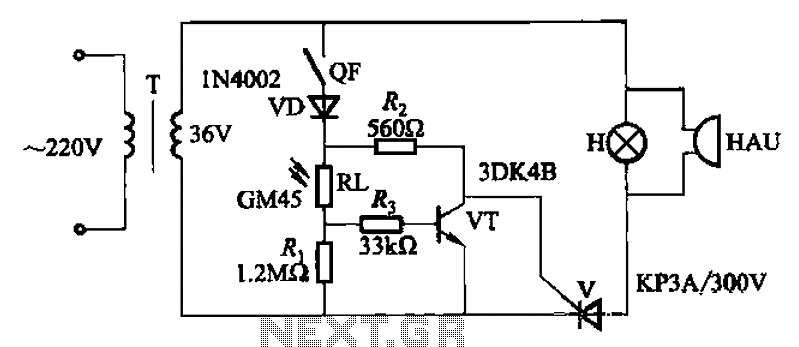
High-voltage isolation switches must not be connected to loads that could create an arc, which may lead to a short circuit between the high-voltage bus and result in accidents that endanger both equipment and personnel safety. Consequently, high-voltage switchgear incorporates...
High-Voltage Generator with HEX FET
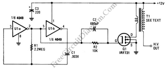
The schematic diagram below illustrates a circuit for a high voltage generator. This circuit employs a 4049 hex inverter as an oscillator, and it can be utilized for ignition purposes.
The high voltage generator circuit is designed to convert a low...
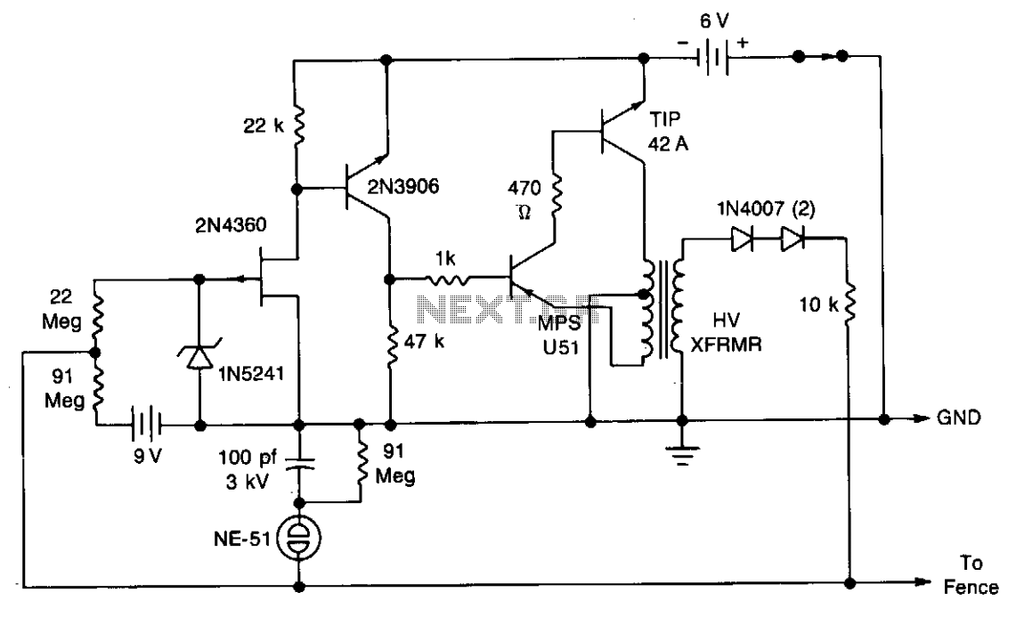
Solid-state electric fence charger
A touch-sensing circuit maintains the high-voltage generator in an off state until contact is made with the fence wire. When something touches the fence sensing circuit wire, it activates the high-voltage generator, which delivers a series of 500-microsecond pulses at...

High-Voltage Pulse Generator
If you have ever wanted a high-voltage generator to create impressive lightning effects, conduct Kirlian photography experiments, or experiment with neon lights, this project is ideal. It describes a laboratory pulse generator utilizing an auto-ignition coil, capable of delivering a...
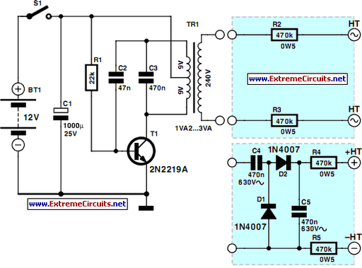
Mini High-Voltage Generator
This project is designed to prevent unauthorized access to personal belongings left on a beach towel while swimming, and it can also be utilized in office or workshop settings. The circuit is compact and can be powered by simple primary...
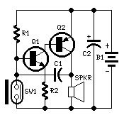
Personal Alarm
This circuit, enclosed in a small plastic box, can be placed into a bag or handbag. A small magnet is placed close to the reed switch and connected to the hand or the clothes of the person carrying the bag...
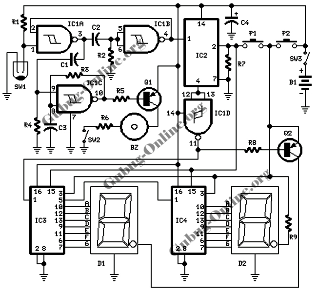
Electrification Circuit Unit
This circuit design is intended for conducting harmless experiments with high-voltage pulses, functioning similarly to an electrified fence generator. The pulse repetition frequency (PRF) is determined by the time constant of the resistor-capacitor network R1-C3 in the feedback loop of...

Alarm Sounder For Flex Switch Circuit
This is a cross-sectional diagram of a flex switch. They can be used as pushbuttons or even position sensors. This schematic diagram shows an oscillator, which is used as an alarm sounder, triggered by a flex switch.
The flex switch is...