


How to Build Toxic Gas Detector and Alarm Circuit with TGS813
#toxic gas detector
#TGS813
#alarm circuit
#sensor
#propane
#gas detection
#safety
#12V battery
#Zener diode
#energy saving
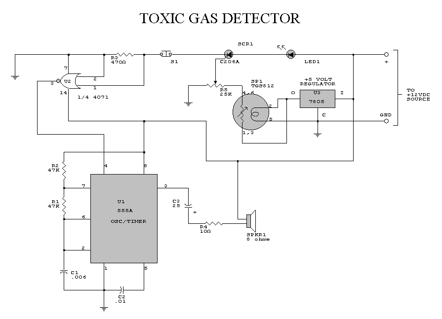
Description: The danger always exists when fuel gases such as propane or natural gas are confined to a small area. The toxic gas alarm utilizes a tin-oxide semiconductor. A coil of thin wire is heated by a 12 V battery through integrated circuits IC1 and IC2, which pulse the voltage to the sensor coil, significantly saving energy. Diode Zener D1 provides a constant voltage to the filament coil sensor. The resistance of the sensor decreases when exposed to toxic gases such as hydrogen, carbon monoxide, and propane. To reduce the sensor's resistance, the gate voltage of the silicon-controlled rectifier (SCR) increases. When the gate threshold voltage is reached, the SCR activates, triggering a buzzer alarm. Once activated, the buzzer and switch S1 must be used to reset the alarm. Due to the sensor's thermal inertia, S1 must remain off for about three to four minutes after the initial activation to allow the sensor to stabilize and avoid false alarms. The sensitivity control R7 should be set to the desired value before activating the SCR. The toxic gas alarm is sensitive to levels below 100 ppm of carbon monoxide, making it useful for applications in gas boats, sheds, and cabins. This device could potentially save lives. Several companies listed in the appendix provide plans and kits for various toxic gas sensors.
The described toxic gas alarm circuit is designed to detect the presence of harmful gases in confined spaces, utilizing a tin-oxide semiconductor sensor that changes resistance in the presence of specific gases. The 12 V battery powers the circuit, which includes two integrated circuits (IC1 and IC2) that control the pulsing voltage supplied to a heated coil. This heating element is essential for the operation of the sensor, as it enhances the sensitivity of the tin-oxide material.
The Zener diode D1 plays a critical role in maintaining a stable voltage across the filament coil, ensuring consistent heating and reliable sensor performance. The operation of the sensor is based on the principle that exposure to toxic gases like hydrogen, carbon monoxide, and propane reduces the resistance of the tin-oxide material. As the concentration of these gases increases, the resistance drops, which in turn raises the gate voltage of the SCR.
When this gate voltage reaches a predetermined threshold, the SCR activates, allowing current to flow through the buzzer, which emits an alarm sound to alert users of dangerous gas levels. To prevent false alarms due to thermal inertia, the switch S1 must remain open for a few minutes after the alarm is triggered, giving the sensor time to stabilize.
The sensitivity of the alarm can be adjusted using the resistor R7, allowing users to calibrate the device according to their specific needs. With the capability to detect carbon monoxide levels below 100 ppm, this alarm is particularly suited for environments such as gas boats, sheds, and cabins where gas leaks could pose serious safety risks. The availability of plans and kits from various manufacturers enhances accessibility for individuals and organizations looking to implement toxic gas detection solutions.The danger always exists, when the fuel gases such as propane or gas are confined to a small area. The alarm of toxic gases figs. 1-45 utilizes a tin-oxide-semiconductor. A coil of thin wire heated by a battery 12 V via IC1 and IC2, which pulses the voltage to the coil of the sensor, saving a significant amount of energy. Diode Zener Dl provides a constant voltage to the filament coil sensor. resistance of the sensor reduces the sensor is exposed to toxic gases such as hydrogen, carbon Carbon monoxide and propane. To reduce the resistance of the sensor, the SCR gate voltage increases. When the gate threshold voltage is reached, the SCR fires and a buzzer alarm is activated. Once activated, the bell and the switch S1 should be used to reset the alarm. Since the sensor has a good deal of thermal inertia, S1 must be off or open for about three or four minutes after the initial activation, allowing the sensor to stabilize, thus avoiding false alarms.
R7 sensitivity control set to the desired value, before the activation of SCR. The toxic gas alarm is sensitive to less than 100 ppm of carbon monoxide. This alarm is useful for simple gas boats, sheds and cabins. You could save a life. Some of the companies listed in the Appendix to offer plans and kits for various toxic gas sensors.
The described toxic gas alarm circuit is designed to detect the presence of harmful gases in confined spaces, utilizing a tin-oxide semiconductor sensor that changes resistance in the presence of specific gases. The 12 V battery powers the circuit, which includes two integrated circuits (IC1 and IC2) that control the pulsing voltage supplied to a heated coil. This heating element is essential for the operation of the sensor, as it enhances the sensitivity of the tin-oxide material.
The Zener diode D1 plays a critical role in maintaining a stable voltage across the filament coil, ensuring consistent heating and reliable sensor performance. The operation of the sensor is based on the principle that exposure to toxic gases like hydrogen, carbon monoxide, and propane reduces the resistance of the tin-oxide material. As the concentration of these gases increases, the resistance drops, which in turn raises the gate voltage of the SCR.
When this gate voltage reaches a predetermined threshold, the SCR activates, allowing current to flow through the buzzer, which emits an alarm sound to alert users of dangerous gas levels. To prevent false alarms due to thermal inertia, the switch S1 must remain open for a few minutes after the alarm is triggered, giving the sensor time to stabilize.
The sensitivity of the alarm can be adjusted using the resistor R7, allowing users to calibrate the device according to their specific needs. With the capability to detect carbon monoxide levels below 100 ppm, this alarm is particularly suited for environments such as gas boats, sheds, and cabins where gas leaks could pose serious safety risks. The availability of plans and kits from various manufacturers enhances accessibility for individuals and organizations looking to implement toxic gas detection solutions.The danger always exists, when the fuel gases such as propane or gas are confined to a small area. The alarm of toxic gases figs. 1-45 utilizes a tin-oxide-semiconductor. A coil of thin wire heated by a battery 12 V via IC1 and IC2, which pulses the voltage to the coil of the sensor, saving a significant amount of energy. Diode Zener Dl provides a constant voltage to the filament coil sensor. resistance of the sensor reduces the sensor is exposed to toxic gases such as hydrogen, carbon Carbon monoxide and propane. To reduce the resistance of the sensor, the SCR gate voltage increases. When the gate threshold voltage is reached, the SCR fires and a buzzer alarm is activated. Once activated, the bell and the switch S1 should be used to reset the alarm. Since the sensor has a good deal of thermal inertia, S1 must be off or open for about three or four minutes after the initial activation, allowing the sensor to stabilize, thus avoiding false alarms.
R7 sensitivity control set to the desired value, before the activation of SCR. The toxic gas alarm is sensitive to less than 100 ppm of carbon monoxide. This alarm is useful for simple gas boats, sheds and cabins. You could save a life. Some of the companies listed in the Appendix to offer plans and kits for various toxic gas sensors.
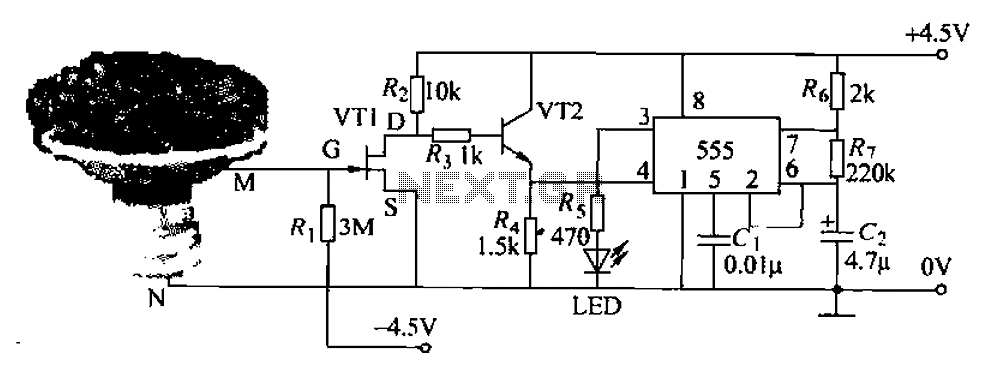
Pots water alarm circuit
The flowers in pots require watering, as relying solely on the observation of moist soil surfaces can be unreliable. To address this issue, a flower watering indicator has been developed. This circuit includes a field effect transistor (VT1), a second...
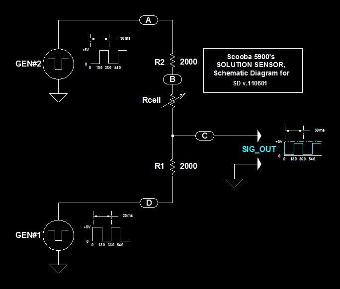
Scoobas Solution Sensing Tactic
This document serves multiple purposes, primarily to document the methods employed by a Scooba robot to detect: a) the presence of an acceptable cleaning solution being delivered to its pump, and b) the excess presence of used solution collected off...
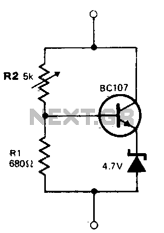
Variable zener diode
The circuit operates similarly to a zener diode across a wide range of voltages. The current flowing through the voltage divider formed by resistors R1 and R2 is significantly greater than the base current of the transistor, approximately 8 mA....
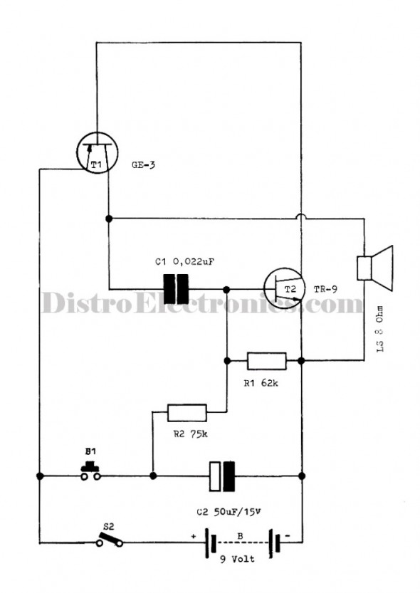
Easy Alarms Police / Ambulance Electronic
The following circuit illustrates the electronic diagram design for police and ambulance alarms. Features include simplicity and ease of assembly, as well as cost-effectiveness.
This electronic schematic represents a basic alarm system intended for use in police and ambulance applications. The...
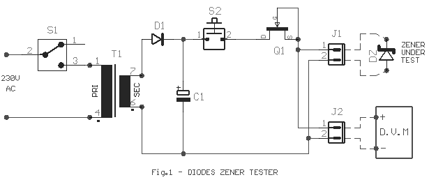
diode zener tester
Frequently, there are situations where the need arises to utilize a Zener diode, yet the operational voltage is unknown. Often, the characteristics or type inscribed on the diode are not legible.
Zener diodes are essential components in electronic circuits, primarily used...
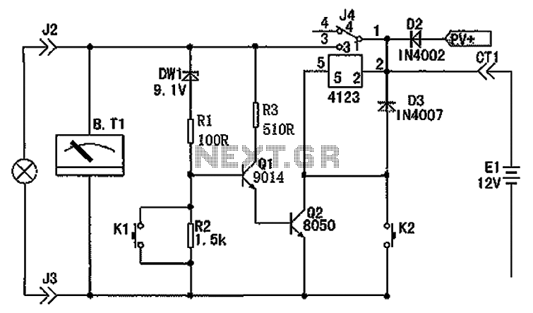
12V battery production controller
The circuit depicted in the figure consists of a battery, a controller, and various electrical and charging components. It includes a Zener diode (D1) and resistors (R1, R2) for undervoltage detection. The circuit also features transistors (Q1, Q2), resistors (R3),...
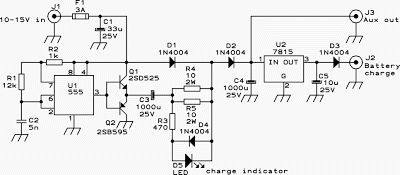
12V Powered 12V Lead Acid Battery Charger with Indicator
A charger is essential for charging a 12 Volt battery from a 12 Volt source due to the typical voltage variation between 11 Volt and 15 Volt. A battery requires a controlled charge current and voltage, which cannot be achieved...

henry alc zener
The Automatic Loading Control (ALC) 100 volt 5 watt zener diode in Henry RF amplifiers is known to fail. Initially, it shorts, causing a high voltage (HV) surge, which typically results in the zener blowing open and tripping the main...

Battery Charge Nominal Discharge Indicator Circuit
12V Battery Charge Nominal Discharge (Low) Indicator Circuit. This circuit monitors car battery voltage and provides an indication of nominal supply voltage, as well as low or high voltage.
The 12V Battery Charge Nominal Discharge Indicator Circuit is designed to continuously...