


iButton Electronic Lock Schematic Diagram
#iButton
#electronic lock
#AT89C2051
#voltage regulator
#bridge rectifier
#battery
#ADM1232
#microcontroller
#security system
#access control
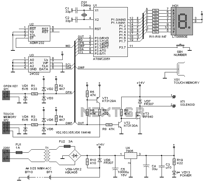
Description: The following circuit illustrates the iButton Electronic Lock Schematic diagram. This circuit is based on the Atmel AT89C2051 integrated circuit (IC). Features include an onboard power supply comprising a transformer (T1) and a voltage regulator (U4), a bridge rectifier (VD9-VD12), a current rating of 20mA, and a battery pack (BT1-BT10) consisting of AA batteries. Additionally, an ADM1232 IC is utilized for controlling the microcontroller reset pin. Components involved include ICs, capacitors, resistors, transistors, diodes, and a transformer.
The iButton Electronic Lock circuit is designed to provide a secure locking mechanism controlled by a microcontroller, specifically the Atmel AT89C2051. This microcontroller serves as the core processing unit, executing the logic required to manage the locking system based on inputs from the iButton device.
The power supply section of the circuit is essential for ensuring stable operation. The transformer (T1) steps down the mains voltage to a lower AC voltage, which is then rectified by the bridge rectifier (VD9-VD12). This rectification process converts the AC voltage into a DC voltage suitable for powering the microcontroller and other components. The voltage regulator (U4) is employed to maintain a constant voltage level, which is critical for the reliable operation of the microcontroller and associated circuitry.
The circuit is designed to operate at a current of 20mA, which is sufficient for the microcontroller and peripheral devices without overloading the power supply components. The battery pack (BT1-BT10) consisting of AA batteries provides an alternative power source, ensuring that the lock remains operational even during power outages.
The ADM1232 IC plays a crucial role in the circuit by managing the reset pin of the microcontroller. This ensures that the microcontroller starts in a known state and can recover from any unforeseen issues, enhancing the overall reliability of the locking mechanism.
Other components in the circuit, such as capacitors, resistors, transistors, and diodes, are used for filtering, signal conditioning, and switching applications, which contribute to the overall functionality and efficiency of the electronic lock system. The inclusion of these components allows for improved noise immunity and ensures that the circuit operates smoothly under various conditions.
Overall, the iButton Electronic Lock circuit is a well-designed system that integrates various electronic components to achieve a secure and reliable locking mechanism, suitable for various applications requiring enhanced security measures.The following circuit shows about iButton Electronic Lock Schematic diagram. This circuit based on the Atmel AT89C2051 IC. Features: power supply on board (transformer T1, voltage regulator U4), bridge rectifier VD9-VD12, 20mA current, BT1-BT10 AA batteries, ADM1232 IC for mcu reset pin control, Component: IC, Capacitor, Resistor, Tra nsistor, Diode, Transformer. [high-voltage-lab. com]
The iButton Electronic Lock circuit is designed to provide a secure locking mechanism controlled by a microcontroller, specifically the Atmel AT89C2051. This microcontroller serves as the core processing unit, executing the logic required to manage the locking system based on inputs from the iButton device.
The power supply section of the circuit is essential for ensuring stable operation. The transformer (T1) steps down the mains voltage to a lower AC voltage, which is then rectified by the bridge rectifier (VD9-VD12). This rectification process converts the AC voltage into a DC voltage suitable for powering the microcontroller and other components. The voltage regulator (U4) is employed to maintain a constant voltage level, which is critical for the reliable operation of the microcontroller and associated circuitry.
The circuit is designed to operate at a current of 20mA, which is sufficient for the microcontroller and peripheral devices without overloading the power supply components. The battery pack (BT1-BT10) consisting of AA batteries provides an alternative power source, ensuring that the lock remains operational even during power outages.
The ADM1232 IC plays a crucial role in the circuit by managing the reset pin of the microcontroller. This ensures that the microcontroller starts in a known state and can recover from any unforeseen issues, enhancing the overall reliability of the locking mechanism.
Other components in the circuit, such as capacitors, resistors, transistors, and diodes, are used for filtering, signal conditioning, and switching applications, which contribute to the overall functionality and efficiency of the electronic lock system. The inclusion of these components allows for improved noise immunity and ensures that the circuit operates smoothly under various conditions.
Overall, the iButton Electronic Lock circuit is a well-designed system that integrates various electronic components to achieve a secure and reliable locking mechanism, suitable for various applications requiring enhanced security measures.The following circuit shows about iButton Electronic Lock Schematic diagram. This circuit based on the Atmel AT89C2051 IC. Features: power supply on board (transformer T1, voltage regulator U4), bridge rectifier VD9-VD12, 20mA current, BT1-BT10 AA batteries, ADM1232 IC for mcu reset pin control, Component: IC, Capacitor, Resistor, Tra nsistor, Diode, Transformer. [high-voltage-lab. com]

Logic PSU With Over-Voltage Protection
A simple 5 Volt regulated power supply unit (PSU) featuring overvoltage protection. This 5 Volt regulated power supply is designed for TTL and 74LS series integrated circuits.
The 5 Volt regulated power supply unit is an essential component in electronic designs...
DC Power Supply 9 volt using TIP31 transistor
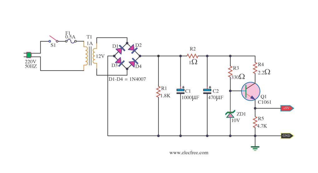
This is a DC power supply circuit designed to regulate 9 volts and provide a current output ranging from 1 amp to 2 amps. The circuit utilizes a modified TIP31 transistor, although alternative transistors such as TIP41, MJE3055, or 2SC1061...
Exploring Microcontrollers
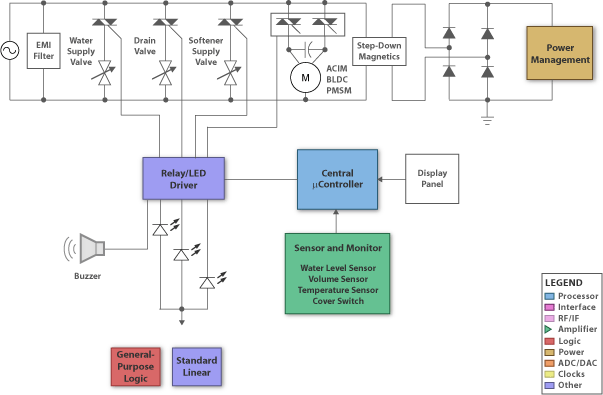
Many of today's appliances feature displays and buttons. Instead of relying on motors and gears, numerous household items now incorporate embedded microcontrollers. This exploration focuses on how to experiment with microcontrollers at home.
Microcontrollers serve as the central processing units for...
repair microcontroller circuit
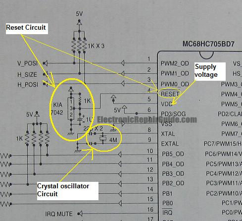
The difference between these two ICs. A microcontroller is a specialized type of microprocessor designed to be self-sufficient and cost-effective, while a microprocessor is typically intended for general-purpose use, such as in personal computers (PCs). The microcontroller integrates several useful...
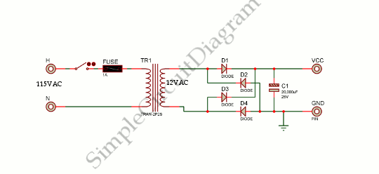
Low Voltage Power Supply
This is a power supply circuit that produces a voltage range of 12 to 24 V. It is straightforward, requiring only a bridge rectifier, a filter capacitor, and a transformer, without the need for a regulator. A bridge rectifier utilizes...
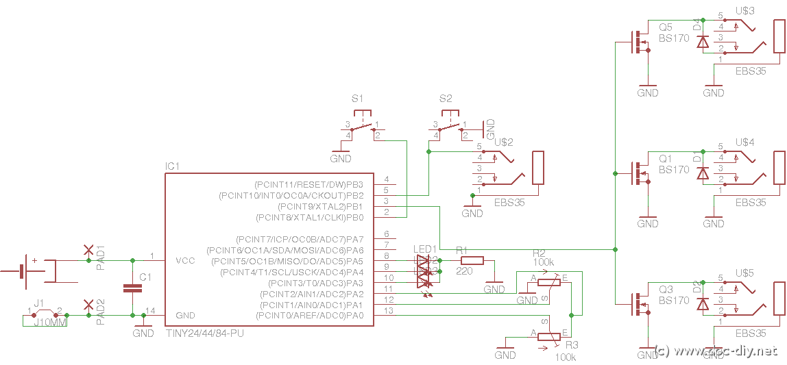
delay
This article outlines the construction of a simple microcontroller-based delay circuit designed for photographic applications, such as drop or high-speed photography. It is capable of controlling the trigger lag for cameras and flash units, generating periodic trigger pulses, or managing...
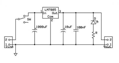
ic-7805 based 5V breadboard mini PSU circuit with explanation
A micro power supply unit (PSU) is designed to power a breadboard with a voltage output of 5 volts. It can be connected to a 9V battery, a 12V source, or any other direct current (DC) power supply ranging from...
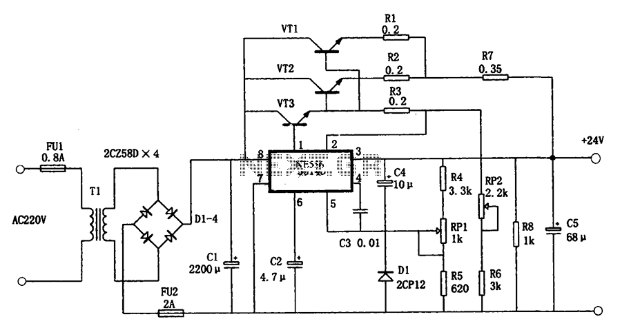
5G14D + 24V 1.9A power supply
The circuit illustrated in the figure is a +24V, 1.9A power supply design. It employs the 5G14D domestic integrated voltage regulator as the core component, supported by three external power transistors. While the 5G14D voltage regulator has a rated current...
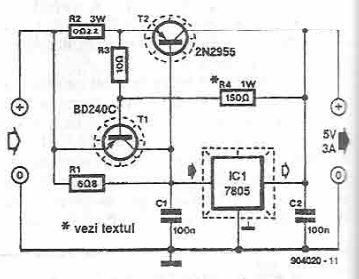
5 volts high current power supply using 7805 voltage regulator
This power supply circuit is designed to provide a high current 5-volt output using a 7805 voltage regulator along with several standard electronic components. The transistor T1 functions as a current limiter. When the voltage across resistors R2 and R3...