


Infrared Motion Detector Circuit-IR motion sensor circuit with motion detector alarm
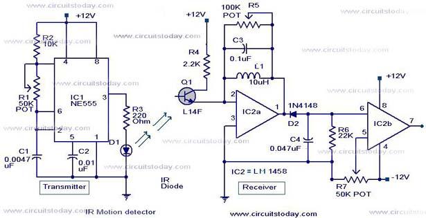
Description: Infrared (IR) Motion Detector Circuit featuring a motion detector alarm and an infrared sensor. The circuit diagram and its operation are provided in detail.
The infrared (IR) motion detector circuit is designed to detect motion within a specified range and trigger an alarm when motion is detected. The core components of this circuit include an infrared sensor, a microcontroller or comparator, a power supply, and an alarm output device such as a buzzer or LED.
The infrared sensor operates by emitting infrared light and detecting the reflection of that light from objects within its field of view. When a person or object moves within this range, the sensor detects the change in the reflected infrared light and sends a signal to the microcontroller or comparator.
The microcontroller processes the signal from the infrared sensor. If motion is detected, it activates the alarm output. The alarm can be configured to be a sound (buzzer) or light (LED), depending on the application requirements. The circuit may also include additional features such as sensitivity adjustment and delay timers to prevent false alarms from minor movements.
Power supply considerations are critical for this circuit. Typically, a battery or DC power source is used to provide the necessary voltage and current to the components. Proper voltage regulation may be incorporated to ensure stable operation of the circuit.
The schematic representation of the IR motion detector circuit will include the layout of the infrared sensor, the connections to the microcontroller or comparator, the alarm output configuration, and the power supply connections. The design should also indicate the values of any resistors, capacitors, or other passive components used to fine-tune the circuit's performance.
Overall, this infrared motion detector circuit is suitable for various applications, including security systems, automatic lighting control, and energy-saving devices, making it a versatile solution for detecting motion in a defined area.Infrared (IR) Motion Detector Circuit with motion detector alarm and infrared sensor.The motion sensor circuit diagram and working is given in detail..
The infrared (IR) motion detector circuit is designed to detect motion within a specified range and trigger an alarm when motion is detected. The core components of this circuit include an infrared sensor, a microcontroller or comparator, a power supply, and an alarm output device such as a buzzer or LED.
The infrared sensor operates by emitting infrared light and detecting the reflection of that light from objects within its field of view. When a person or object moves within this range, the sensor detects the change in the reflected infrared light and sends a signal to the microcontroller or comparator.
The microcontroller processes the signal from the infrared sensor. If motion is detected, it activates the alarm output. The alarm can be configured to be a sound (buzzer) or light (LED), depending on the application requirements. The circuit may also include additional features such as sensitivity adjustment and delay timers to prevent false alarms from minor movements.
Power supply considerations are critical for this circuit. Typically, a battery or DC power source is used to provide the necessary voltage and current to the components. Proper voltage regulation may be incorporated to ensure stable operation of the circuit.
The schematic representation of the IR motion detector circuit will include the layout of the infrared sensor, the connections to the microcontroller or comparator, the alarm output configuration, and the power supply connections. The design should also indicate the values of any resistors, capacitors, or other passive components used to fine-tune the circuit's performance.
Overall, this infrared motion detector circuit is suitable for various applications, including security systems, automatic lighting control, and energy-saving devices, making it a versatile solution for detecting motion in a defined area.Infrared (IR) Motion Detector Circuit with motion detector alarm and infrared sensor.The motion sensor circuit diagram and working is given in detail..
Pots water alarm circuit
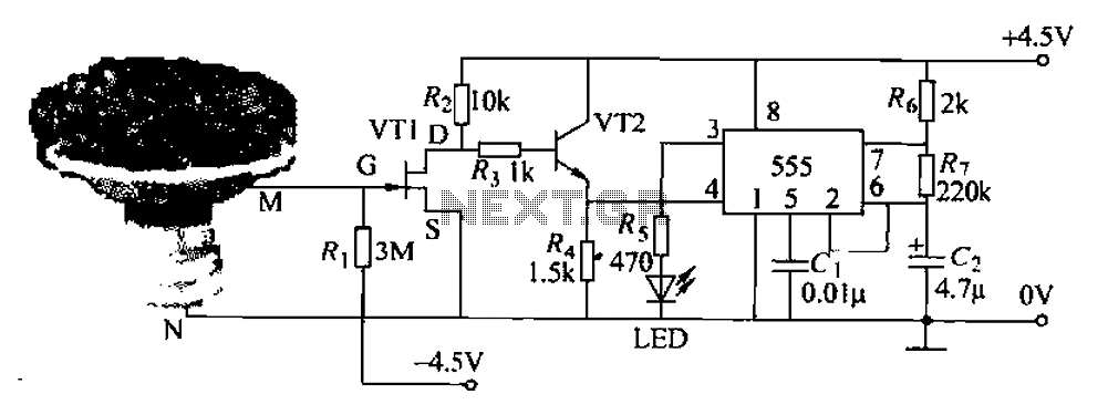
The flowers in pots require watering, as relying solely on the observation of moist soil surfaces can be unreliable. To address this issue, a flower watering indicator has been developed. This circuit includes a field effect transistor (VT1), a second...
Infrared Detection with 74HC04
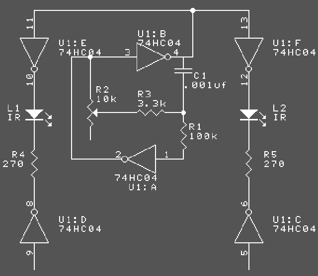
The two basic parts for working with IR are the emitter and the detector. The emitter is typically an LED that emits near-infrared light. A typical wavelength is 880nm, which is just beyond the human eye's ability to see. Many...
Power disconnection alarm circuit diagram
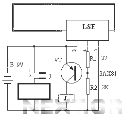
The circuit operation principle of the device illustrated in Figure 13 is as follows: When the barbed wire (Fe) remains intact, the output pin (O) of the LSE is at a high state. Consequently, the transistor (VT) remains off, and...
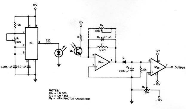
active ir motion detector
The circuit illustrates the operation of an ultrasonic motion detector, which consists of two transducers: one that emits ultrasonic waves and another that detects reflections from various objects in the vicinity. When no objects are in motion, the reflected waves...
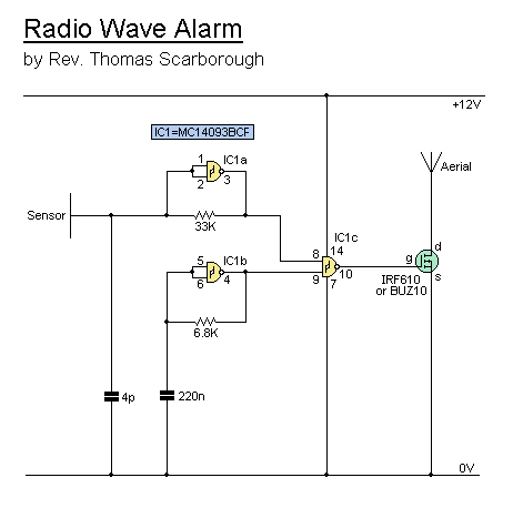
radio wave alarm
This simple alarm circuit can effectively alert users to the presence of an intruder, providing notification before they even reach the doorstep.
The circuit is designed to be straightforward and efficient, utilizing basic electronic components to create an effective security solution....
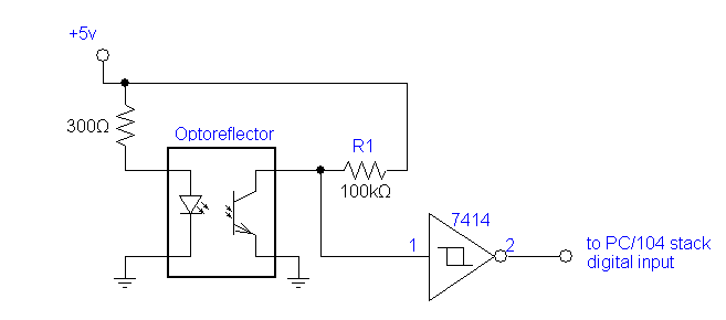
Optoreflector
Optoreflector sensors consist of a matched infrared transmitter (LED) and an infrared receiver (typically a phototransistor) pair. These devices function by measuring the amount of light reflected into the receiver. Since the receiver is also sensitive to ambient light, optimal...
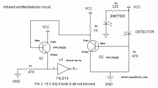
infrared emitter and detector using ic 74ls14
This circuit is designed for line detection in a robot project. A proper match between the transmitter and the detector is crucial for optimal operation, particularly when the hole is large. The robot is equipped with a simple system for...
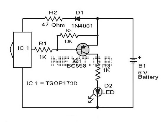
Remote Control Tester Circuit using Infra red sensor IC TSOP 1738
A simple remote control tester circuit with a diagram and schematic using the infrared sensor IC TSOP1738. An LED will blink when infrared waves fall on it, indicating the remote control is functioning.
The remote control tester circuit utilizes the TSOP1738...
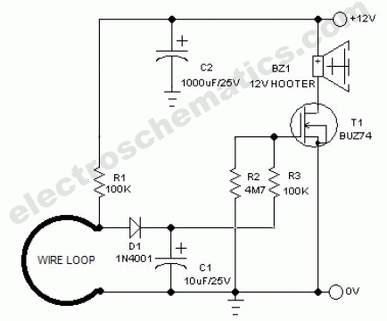
Wire Break Sensor Alarm Circuit Schematic
The circuit of a loop sensor-based simple security alarm is described here. The sensor loop consists of a short length of thin enamelled copper wire.
The loop sensor security alarm operates on the principle of detecting interruptions in the circuit formed...