


Infrared sensor high voltage dangerous voice warning circuit diagram
#infrared sensor
#555 timer
#monostable trigger
#high voltage
#voice warning
#security
#human detection
#pulse signal
#alarm circuit
#sensor head
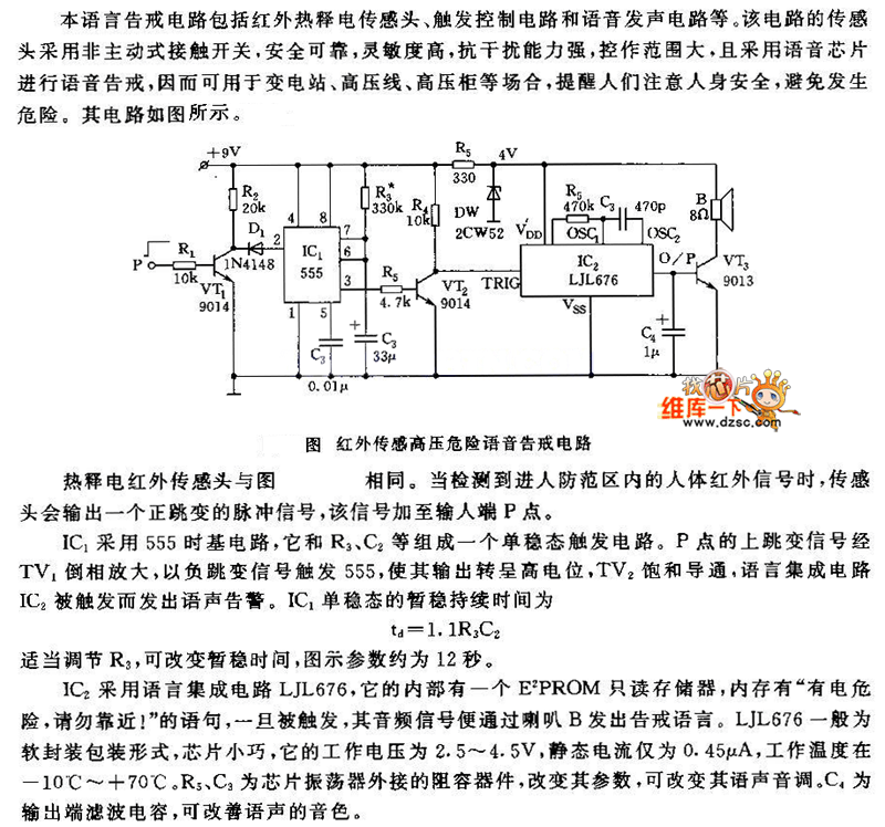
Description: The pyroelectric infrared sensor head operates as illustrated in the accompanying figure. Upon detecting an infrared signal from a human body within its monitoring zone, the sensor head generates a positive pulse signal. This signal is transmitted to the input terminal designated as point P. The integrated circuit IC1 utilizes a 555 timer in a monostable configuration, with the trigger circuit comprising the 555 timer, resistor R3, and capacitor C2. The pulse signal at point P is processed and amplified.
The pyroelectric infrared sensor head is designed to detect infrared radiation emitted by human bodies, making it suitable for applications such as motion detection, security systems, and automatic lighting. The sensor head typically consists of a pyroelectric element that generates a voltage when exposed to varying infrared radiation levels. This voltage change, when a human body enters the detection zone, is converted into a positive pulse signal.
The 555 timer IC, configured in a monostable mode, is an essential component of this circuit. In this configuration, the output remains low until a triggering event occurs, which in this case is the positive pulse signal from the sensor head. The resistor R3 and capacitor C2 determine the duration of the output pulse. When the signal at point P is received, the 555 timer generates a single output pulse whose width is defined by the time constant of R3 and C2. This output can be used to trigger additional circuits or systems, such as alarms or lights, enhancing the functionality of the sensor system.
The amplification of the pulse signal ensures that it is strong enough to drive subsequent components in the circuit. The design of this sensor system is critical for ensuring reliable operation in various environments, and careful selection of components such as R3 and C2 is necessary to tailor the response time and sensitivity of the system to meet specific application requirements.Pyroelectric infrared sensor head is same with the figure. When it detects the human body infrared signal in guarding zone, the sensor head will output a positive jump pulse signal, this signal is added to input terminal P point. IC1 adopts 555 time base circuit, the monostable trigger circuit is composed of 555 and R3, C2. P`s jump signal is phased and amp..
The pyroelectric infrared sensor head is designed to detect infrared radiation emitted by human bodies, making it suitable for applications such as motion detection, security systems, and automatic lighting. The sensor head typically consists of a pyroelectric element that generates a voltage when exposed to varying infrared radiation levels. This voltage change, when a human body enters the detection zone, is converted into a positive pulse signal.
The 555 timer IC, configured in a monostable mode, is an essential component of this circuit. In this configuration, the output remains low until a triggering event occurs, which in this case is the positive pulse signal from the sensor head. The resistor R3 and capacitor C2 determine the duration of the output pulse. When the signal at point P is received, the 555 timer generates a single output pulse whose width is defined by the time constant of R3 and C2. This output can be used to trigger additional circuits or systems, such as alarms or lights, enhancing the functionality of the sensor system.
The amplification of the pulse signal ensures that it is strong enough to drive subsequent components in the circuit. The design of this sensor system is critical for ensuring reliable operation in various environments, and careful selection of components such as R3 and C2 is necessary to tailor the response time and sensitivity of the system to meet specific application requirements.Pyroelectric infrared sensor head is same with the figure. When it detects the human body infrared signal in guarding zone, the sensor head will output a positive jump pulse signal, this signal is added to input terminal P point. IC1 adopts 555 time base circuit, the monostable trigger circuit is composed of 555 and R3, C2. P`s jump signal is phased and amp..

Variable-duty-cycle-timer
When configured as a free-running multivibrator, a 555 timer provides no more than a 50% duty cycle. By adding two transistors, however, it is possible to obtain a variable duty cycle ranging from 5% to 95% without altering the total...
Beam sputter for oscilloscope
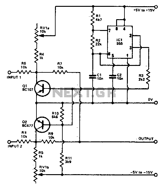
The foundation of the beam splitter utilizes a 555 timer configured as an astable multivibrator. Signals at the two inputs are alternately displayed on the oscilloscope, exhibiting a distinct separation between them. The output is regulated by the tandem potentiometer...

Cellular Phone Jammer with 555
And my recent study about chaos is really making me have FUN! The subject is awesome! And my Geeky Bro informed me something about a cell phone jammer, a simple timer circuit using 555. Will work within 10 feet maybe,...
9 Second Digital Readout Countdown Timer
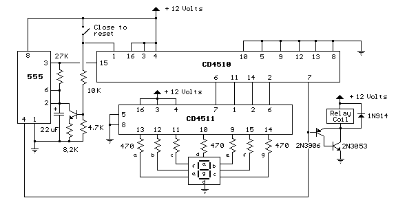
This circuit provides a visual 9-second delay using a 7-segment digital readout LED. When the switch is closed, the CD4010 up/down counter is preset to 9, and the 555 timer is disabled, holding the output high. When the switch is...
555 Music lantern controller circuit diagram
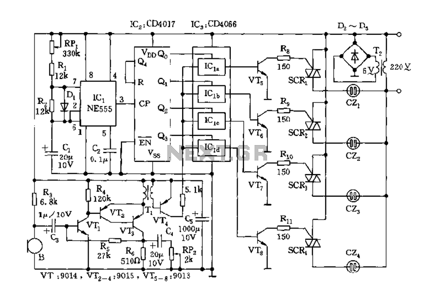
The circuit includes a controller that integrates an acoustic-electric conversion and amplification circuit, a clock pulse generator, a counting circuit, and a control circuit. It manages four accompanying music tracks and flashing lights. Microphones (MIC) convert sound into electrical signals,...
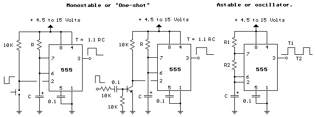
555 Timer Frequency and Duty Cycle Calculator
Input values for R1, R2, and C, then press the calculate button to determine the positive time interval (T1) and negative time interval (T2). For instance, using a 10K resistor (R1) and a 100K resistor (R2) along with a 0.1...
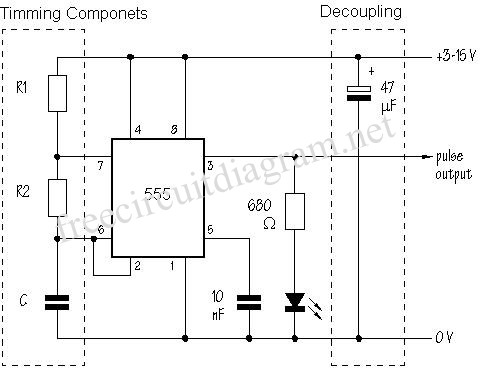
Astable circuits produce pulses using 555
The SE555/NE555 timer was first introduced by the Signetics Corporation around 1971. Pin connections and functions are as follows: Pin 1 (Ground) - This pin serves as the ground or common pin, representing the most negative supply potential of the...
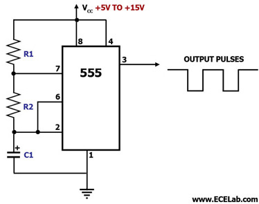
Audio Astable Multivibrator Using IC 555 Circuit
This circuit diagram illustrates the configuration of a 555 timer integrated circuit (IC) as an astable multivibrator. An astable multivibrator is a timing circuit characterized by unstable 'low' and 'high' states. Consequently, the output of an astable multivibrator continuously toggles...
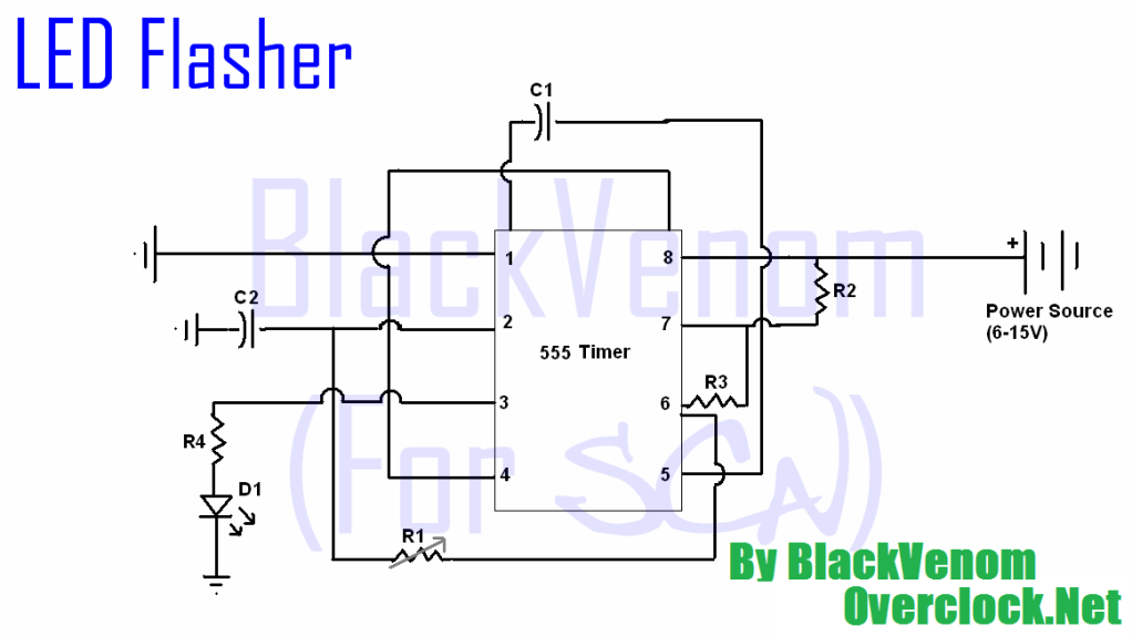
555 Timer LED Flasher Circuit
All of the components in this list are generally available through RadioShack for less than $20. It is highly recommended to use a breadboard for assembly, as mistakes are common for first-time builders, and soldering can complicate troubleshooting. This tutorial...