


Intelligent Presence Simulator
#presence simulator
#burglar deterrent
#home security
#automated lighting
#occupancy simulation
#alarm system
#domestic safety
#intelligent control
#security automation
#motion simulation
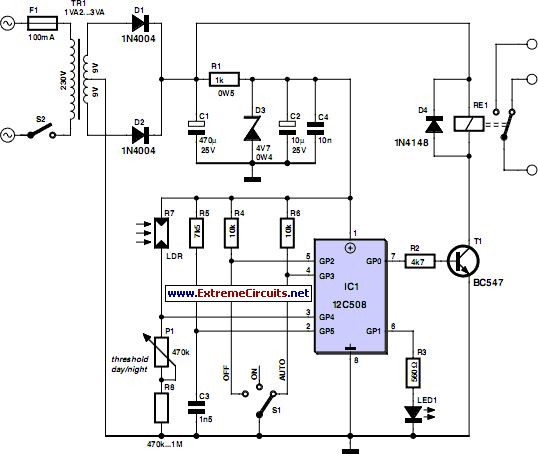
Description: Although a domestic alarm system can be effective, it is always preferable to prevent it from activating in the first place. The best method to achieve this is to create the illusion that the premises are occupied. Most burglaries are perpetrated by petty thieves who prefer to target homes where the occupants are away. Rather than avoiding vacations, it is advisable to construct an intelligent presence simulator that will deter potential burglars, even under close scrutiny. This circuit activates one or more lights when ambient light levels drop, but unlike many devices that use fixed timing, this one employs randomly variable durations. This irregular operation makes it less predictable and more credible. The circuit utilizes a PIC12C508 microcontroller from Microchip, which is sufficient for the task. It is powered from the mains and features basic voltage regulation through a zener diode. A relay controls the lights, which, while less sophisticated than a triac, prevents interference from the mains during events like thunderstorms. Reliability during absence is crucial. An LDR (light-dependent resistor) measures ambient light levels, and an adjustable threshold via potentiometer P1 allows customization based on the LDR's characteristics and placement. Input GP4 of the PIC12C508 is not analog but suitable for logic switching. An LED connected to GP1 indicates the operational mode, which can be selected via override switch S1, allowing three states: permanently off, permanently on, and automatic mode, typically used. Due to the need for long delays in lighting times, the microcontroller operates at a reduced clock frequency. A crystal-controlled clock is unsuitable, so an R-C network (R5/C3) is employed instead, introducing the desired randomness. The proposed PCB accommodates all components except for switches S1, S2, and the LDR, which should be positioned for optimal light sensing. The PCB is designed for a Finder relay capable of switching 10 A, sufficient for most home lighting needs. The program for the PIC12C508 is available for free download from the Elektor website. After assembly, the circuit should function immediately and can be tested in manual mode. The relay should be de-energized in the off position and energized in the on position. Finally, the day/night threshold can be adjusted using potentiometer P1, ideally reaching approximately 1.4 V on a high-impedance voltmeter connected between GP4 and ground. If this voltage cannot be achieved, adjustments to resistor R8 may be necessary due to the variable characteristics of LDRs. This affordable device will not make a home impenetrable but will certainly make it less appealing to burglars compared to homes that remain dark for extended periods, particularly during summer.
The intelligent presence simulator circuit is designed to enhance home security by simulating occupancy through lighting control. The core of the circuit revolves around the PIC12C508 microcontroller, which serves as the brain of the system. The microcontroller is programmed to monitor light levels via an LDR and activate a relay to turn lights on or off based on ambient conditions. The use of a relay allows for safe operation with mains voltage while protecting the microcontroller from potential electrical interference.
The circuit's operation is initiated by the ambient light level falling below a specified threshold, which is adjustable through potentiometer P1. This feature allows the user to calibrate the system according to the specific light conditions of their environment. The randomization of light activation times is achieved by manipulating the microcontroller's clock frequency, which is intentionally reduced to create variability in the timing of light operations. This design choice prevents the system from being easily detected by potential intruders who might observe a predictable lighting pattern.
The inclusion of an LED indicator connected to GP1 provides visual feedback on the operational mode of the circuit, facilitating user interaction and troubleshooting. The three operational states—permanently off, permanently on, and automatic mode—offer flexibility depending on the user's needs. The circuit's simplicity is complemented by its reliability, ensuring that it functions correctly even during power fluctuations or external disturbances.
The PCB layout is optimized for easy assembly, with designated areas for component placement, including the relay and microcontroller. The design accommodates a Finder relay capable of handling significant loads, making it suitable for various lighting applications. The overall construction emphasizes durability and ease of use, allowing for straightforward installation and setup.
In summary, this intelligent presence simulator is an effective and low-cost solution for enhancing home security by creating the illusion of occupancy. Its innovative design, featuring random light activation and user-adjustable settings, makes it a valuable addition to any home security strategy.However effective a domestic alarm system may be, it`s invariably better if it never goes off, and the best way to ensure this is to make potential burglars think the premises are occupied. Indeed, unless you own old masters or objects of great value likely to attract professional` burglars, it has to be acknowledged that the majority of burglarie
s are committed by petty` thieves who are going to be looking more than anything else for simplicity and will prefer to break into homes whose occupants are away. Rather than simply not going on holiday which is also one solution to the problem (!) we`re going to suggest building this intelligent presence simulator which ought to put potential burglars off, even if your home is subjected to close scrutiny.
Like all its counterparts, the proposed circuit turns one or more lights on and off when the ambient light falls, but while many devices are content to generate fixed timings, this one works using randomly variable durations. So while other devices are very soon caught out simply by daily observation (often from a car) because of their too-perfect regularity, this one is much more credible due to the fact that its operating times are irregular.
The circuit is very simple, as we have employed a microcontroller a little` 12C508 from Microchip, which is more than adequate for such an application. It is mains powered and uses rudimentary voltage regulation by a zener diode. A relay is used to control the light(s); though this is less elegant than a triac solution, it does avoid any interference from the mains reaching the microcontroller, for example, during thunderstorms.
We mustn`t forget this project needs to work very reliably during our absence, whatever happens. The ambient light level is measured by a conventional LDR (light dependent resistor), and the lighting switching threshold is adjustable via P1 to suit the characteristics and positioning of the LDR. Note that input GP4 of the PIC12C508 is not analogue, but its logic switching threshold is very suitable for this kind of use.
The LED connected to GP1 indicates the circuit`s operating mode, selected by grounding or not of GP2 or GP3 via override switch S1. So there are three possible states: permanently off, permanently on, and automatic mode, which is the one normally used.
Given the software programmed into the 12C508 (firmware`) and the need to generate very long delays so as to arrive at lighting times or an hour or more, it has been necessary to make the MCU operate at a vastly reduced clock frequency. In that case, a crystal-controlled clock is no longer suitable, so the R-C network R5/C3 is used instead.
For sure, such a clock source is less stable than a crystal, but then in an application like this, that may well be what we`re after as a degree of randomness is a design target instead of a disadvantage. Our suggested PCB shown here takes all the components for this project except of course for S1, S2, and the LDR, which will need to be positioned on the front panel of the case in order to sense the ambient light intensity.
The PCB has been designed for a Finder relay capable of switching 10 A, which ought to prove adequate for lighting your home, unless you live in a replica of the Palace of Versailles. The program to be loaded into the 12C508 is available for free download from the Elektor website as file number 080231-11.
zip or from the author`s own website: On completion of the solder work the circuit should work immediately and can be checked by switching to manual mode. The relay should be released in the off` position and energized in the on` position. Then all that remains is to adjust the day/night threshold by adjusting potentiometer P1. To do this, you can either use a lot of patience, or else use a voltmeter digital or analogue, but the latter will need to be electronic so as to be high impedance connected between GP4 and ground.
When the light level below which you want the lighting to be allowed to come on is reached, adjust P1 to read approximately 1. 4 V on the voltmeter. If this value cannot be achieved, owing to the characteristics of your LDR, reduce or increase R8 if necessary to achieve it (LDRs are known to have rather wide production tolerances).
Equipped with this inexpensive accessory, your home of course hasn`t become an impregnable fortress, but at least it ought to appear less attractive to burglars than houses that are plunged into darkness for long periods of time, especially in the middle of summer. (
The intelligent presence simulator circuit is designed to enhance home security by simulating occupancy through lighting control. The core of the circuit revolves around the PIC12C508 microcontroller, which serves as the brain of the system. The microcontroller is programmed to monitor light levels via an LDR and activate a relay to turn lights on or off based on ambient conditions. The use of a relay allows for safe operation with mains voltage while protecting the microcontroller from potential electrical interference.
The circuit's operation is initiated by the ambient light level falling below a specified threshold, which is adjustable through potentiometer P1. This feature allows the user to calibrate the system according to the specific light conditions of their environment. The randomization of light activation times is achieved by manipulating the microcontroller's clock frequency, which is intentionally reduced to create variability in the timing of light operations. This design choice prevents the system from being easily detected by potential intruders who might observe a predictable lighting pattern.
The inclusion of an LED indicator connected to GP1 provides visual feedback on the operational mode of the circuit, facilitating user interaction and troubleshooting. The three operational states—permanently off, permanently on, and automatic mode—offer flexibility depending on the user's needs. The circuit's simplicity is complemented by its reliability, ensuring that it functions correctly even during power fluctuations or external disturbances.
The PCB layout is optimized for easy assembly, with designated areas for component placement, including the relay and microcontroller. The design accommodates a Finder relay capable of handling significant loads, making it suitable for various lighting applications. The overall construction emphasizes durability and ease of use, allowing for straightforward installation and setup.
In summary, this intelligent presence simulator is an effective and low-cost solution for enhancing home security by creating the illusion of occupancy. Its innovative design, featuring random light activation and user-adjustable settings, makes it a valuable addition to any home security strategy.However effective a domestic alarm system may be, it`s invariably better if it never goes off, and the best way to ensure this is to make potential burglars think the premises are occupied. Indeed, unless you own old masters or objects of great value likely to attract professional` burglars, it has to be acknowledged that the majority of burglarie
s are committed by petty` thieves who are going to be looking more than anything else for simplicity and will prefer to break into homes whose occupants are away. Rather than simply not going on holiday which is also one solution to the problem (!) we`re going to suggest building this intelligent presence simulator which ought to put potential burglars off, even if your home is subjected to close scrutiny.
Like all its counterparts, the proposed circuit turns one or more lights on and off when the ambient light falls, but while many devices are content to generate fixed timings, this one works using randomly variable durations. So while other devices are very soon caught out simply by daily observation (often from a car) because of their too-perfect regularity, this one is much more credible due to the fact that its operating times are irregular.
The circuit is very simple, as we have employed a microcontroller a little` 12C508 from Microchip, which is more than adequate for such an application. It is mains powered and uses rudimentary voltage regulation by a zener diode. A relay is used to control the light(s); though this is less elegant than a triac solution, it does avoid any interference from the mains reaching the microcontroller, for example, during thunderstorms.
We mustn`t forget this project needs to work very reliably during our absence, whatever happens. The ambient light level is measured by a conventional LDR (light dependent resistor), and the lighting switching threshold is adjustable via P1 to suit the characteristics and positioning of the LDR. Note that input GP4 of the PIC12C508 is not analogue, but its logic switching threshold is very suitable for this kind of use.
The LED connected to GP1 indicates the circuit`s operating mode, selected by grounding or not of GP2 or GP3 via override switch S1. So there are three possible states: permanently off, permanently on, and automatic mode, which is the one normally used.
Given the software programmed into the 12C508 (firmware`) and the need to generate very long delays so as to arrive at lighting times or an hour or more, it has been necessary to make the MCU operate at a vastly reduced clock frequency. In that case, a crystal-controlled clock is no longer suitable, so the R-C network R5/C3 is used instead.
For sure, such a clock source is less stable than a crystal, but then in an application like this, that may well be what we`re after as a degree of randomness is a design target instead of a disadvantage. Our suggested PCB shown here takes all the components for this project except of course for S1, S2, and the LDR, which will need to be positioned on the front panel of the case in order to sense the ambient light intensity.
The PCB has been designed for a Finder relay capable of switching 10 A, which ought to prove adequate for lighting your home, unless you live in a replica of the Palace of Versailles. The program to be loaded into the 12C508 is available for free download from the Elektor website as file number 080231-11.
zip or from the author`s own website: On completion of the solder work the circuit should work immediately and can be checked by switching to manual mode. The relay should be released in the off` position and energized in the on` position. Then all that remains is to adjust the day/night threshold by adjusting potentiometer P1. To do this, you can either use a lot of patience, or else use a voltmeter digital or analogue, but the latter will need to be electronic so as to be high impedance connected between GP4 and ground.
When the light level below which you want the lighting to be allowed to come on is reached, adjust P1 to read approximately 1. 4 V on the voltmeter. If this value cannot be achieved, owing to the characteristics of your LDR, reduce or increase R8 if necessary to achieve it (LDRs are known to have rather wide production tolerances).
Equipped with this inexpensive accessory, your home of course hasn`t become an impregnable fortress, but at least it ought to appear less attractive to burglars than houses that are plunged into darkness for long periods of time, especially in the middle of summer. (

6 Zone Alarm with LED Display Circuit With LM7805 IC
This circuit consists of a 6 Zone Alarm system with an LED display. The alarm system features 6 independent zones and includes a 7-segment LED display, along with one timed entry/exit zone.
The 6 Zone Alarm system is designed to provide...
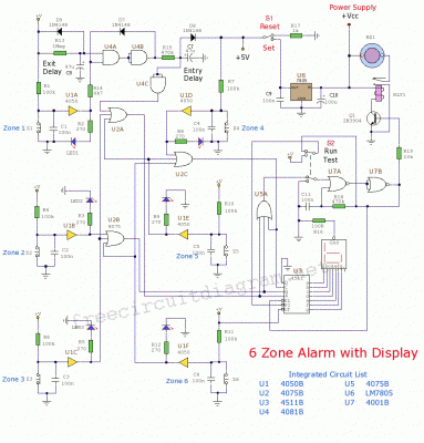
Circuit Diagram 6 zone alarm independent
This circuit is a 6-zone alarm system designed for independent operation, suitable for small office or home environments. It can be adapted to utilize a combination lock or keypad for setting and resetting the alarm. All zones, Z1 to Z6,...
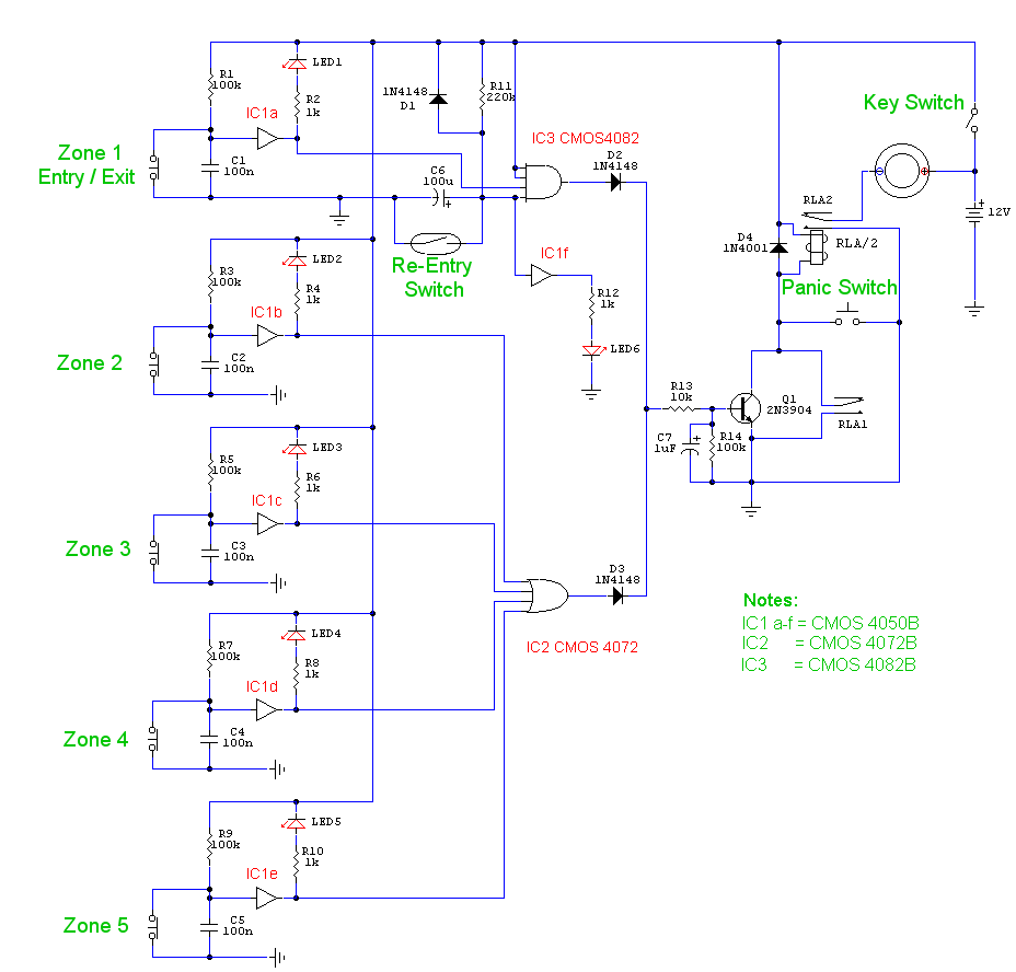
5 zone alarm circuit
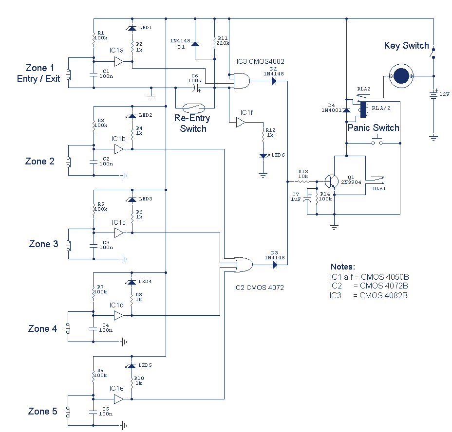
This is a complete alarm system with five independent zones suitable for a small office or home environment. It utilizes three CM integrated circuits and features a timed entry/exit zone, four immediate zones, and a panic button. There are indicators...
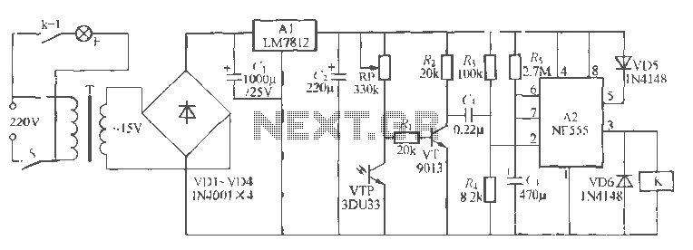
Coop automatically fill light circuit
Hens require adequate illumination to increase egg production rates. To counteract the reduced winter sunlight, poultry farms commonly utilize artificial lighting in coops. For instance, the circuit depicted in Figure 297 can automatically provide light at night. The light activates...
5 Zone Alarm System
This is a complete alarm system with 5 independent zones suitable for a small office or home environment. It uses just 3 CMOS ICs and features a timed entry/exit zone, 4 immediate zones, and a panic button. There are indicators...
mini projects
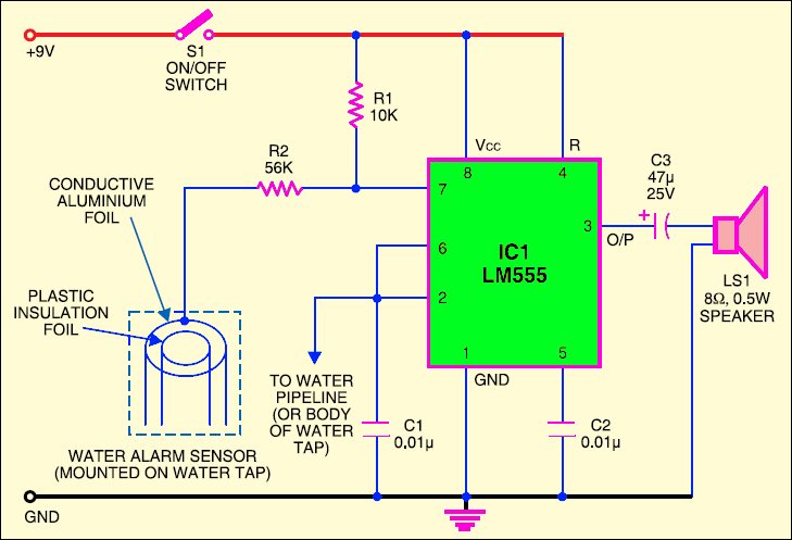
This circuit automates the control of street or porch lights. It utilizes a 7806 voltage regulator IC to manage the operation of street lights, tube lights, or other household lighting systems. The 7806 IC provides a stable output voltage despite...
Programmable Home Security Alarm System
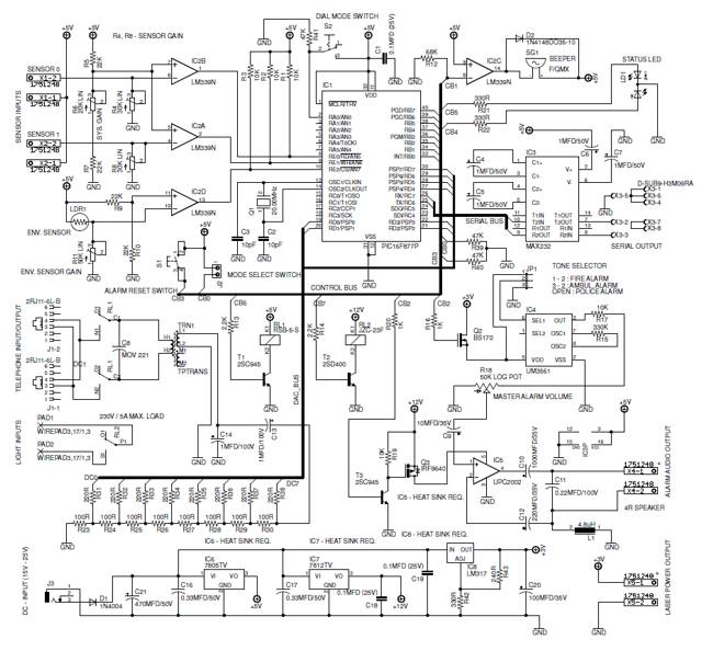
A low-cost, high-performance programmable home security system utilizing a few LDRs as input sensors. When the sensors are triggered, the system can dial a user-specified phone number using a built-in DTMF generator and activate a high-power audio alarm and lights....
6 Zone Alarm System
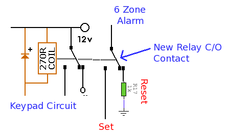
This alarm system features six independent zones, one timed entry/exit zone, a seven-segment LED display, and a test or walkthrough capability. It is designed for use in small office or home environments and can be adapted to utilize a combination...
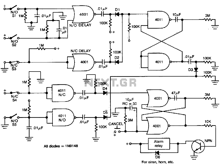
Home security monitor system
This circuit provides normally open (NO) and normally closed (NC) contacts SI, S2, and S3 to activate the alarm after a 30-second delay. S4 and S5 operate instantly. The CANCEL switch resets the alarm.
The described circuit functions as a delay...