


Latching burglar alarm
#latching
#burglar alarm
#protective circuit
#alarm sound
#security
#sensor
#trigger
#circuit interruption

Description: When the protective circuit is interrupted (opened), the alarm sounds. To set the circuit, adjust R2 (with the protective circuit open) for 1 V across R1.
The described circuit functions as a protective alarm system that activates when the integrity of the circuit is compromised. This system includes a resistor R1, which is part of the voltage sensing mechanism, and a variable resistor R2, which is used for calibration.
Upon interruption of the protective circuit, a signal is generated that triggers an alarm. This alarm serves as a warning mechanism to indicate that the circuit has been opened, which may signify a fault or unauthorized access. The alarm can be an audible signal, such as a buzzer or speaker, that alerts nearby personnel to the condition.
For proper calibration of the circuit, R2 must be adjusted while the protective circuit is open to achieve a voltage of 1 V across R1. This adjustment ensures that the circuit operates within the desired parameters, allowing for accurate detection of any interruptions. The resistance values of R1 and R2 should be selected based on the overall design requirements, including the expected voltage range and the characteristics of the alarm system.
In practical applications, the circuit may also include additional components such as diodes for protection against reverse polarity or transient voltages, capacitors for noise filtering, and possibly a microcontroller for more sophisticated monitoring and control functions. The layout of the circuit should ensure minimal interference and reliable operation under varying environmental conditions.
Overall, this protective circuit design is crucial for applications requiring security and monitoring, ensuring that any unauthorized access or faults are promptly detected and communicated through an alarm system.When the protective circuit is interrupted (opened), the alarm sounds To set the circuit, adjust R2 (with protective circuit open) for 1 V across Rl.
The described circuit functions as a protective alarm system that activates when the integrity of the circuit is compromised. This system includes a resistor R1, which is part of the voltage sensing mechanism, and a variable resistor R2, which is used for calibration.
Upon interruption of the protective circuit, a signal is generated that triggers an alarm. This alarm serves as a warning mechanism to indicate that the circuit has been opened, which may signify a fault or unauthorized access. The alarm can be an audible signal, such as a buzzer or speaker, that alerts nearby personnel to the condition.
For proper calibration of the circuit, R2 must be adjusted while the protective circuit is open to achieve a voltage of 1 V across R1. This adjustment ensures that the circuit operates within the desired parameters, allowing for accurate detection of any interruptions. The resistance values of R1 and R2 should be selected based on the overall design requirements, including the expected voltage range and the characteristics of the alarm system.
In practical applications, the circuit may also include additional components such as diodes for protection against reverse polarity or transient voltages, capacitors for noise filtering, and possibly a microcontroller for more sophisticated monitoring and control functions. The layout of the circuit should ensure minimal interference and reliable operation under varying environmental conditions.
Overall, this protective circuit design is crucial for applications requiring security and monitoring, ensuring that any unauthorized access or faults are promptly detected and communicated through an alarm system.When the protective circuit is interrupted (opened), the alarm sounds To set the circuit, adjust R2 (with protective circuit open) for 1 V across Rl.
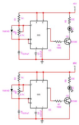
Automatic Room light Control With Bi Directional Visitor Counter
The objective of this project is to create a controller-based model that counts the number of individuals entering a specific room and activates the lighting accordingly. This is achieved through the use of sensors that detect the current number of...
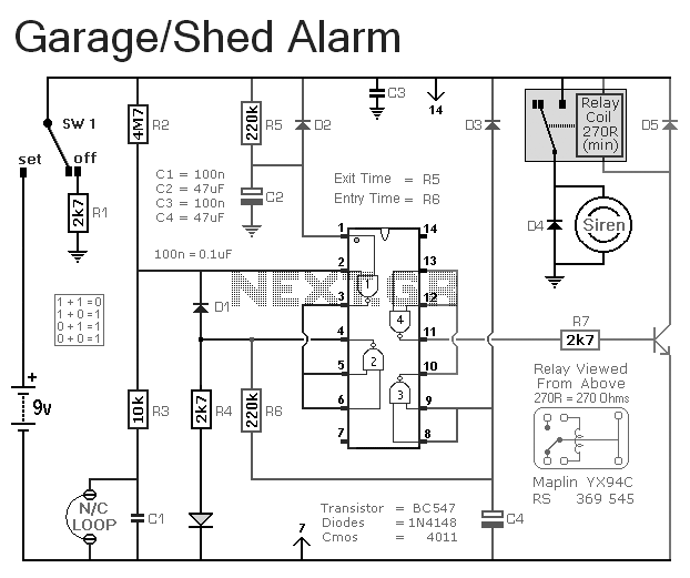
Automatic Garage / Shed Alarm
This is a simple single-zone burglar alarm. The basic design includes automatic exit and entry delays. It does not include a siren cut-off timer, but with a small modification, one can be added to the circuit. The alarm will accept...
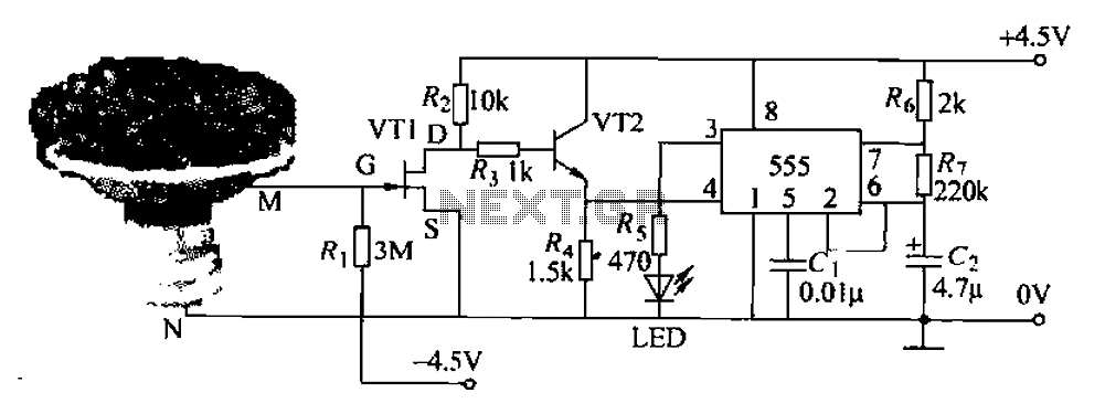
Pots water alarm circuit
The flowers in pots require watering, as relying solely on the observation of moist soil surfaces can be unreliable. To address this issue, a flower watering indicator has been developed. This circuit includes a field effect transistor (VT1), a second...
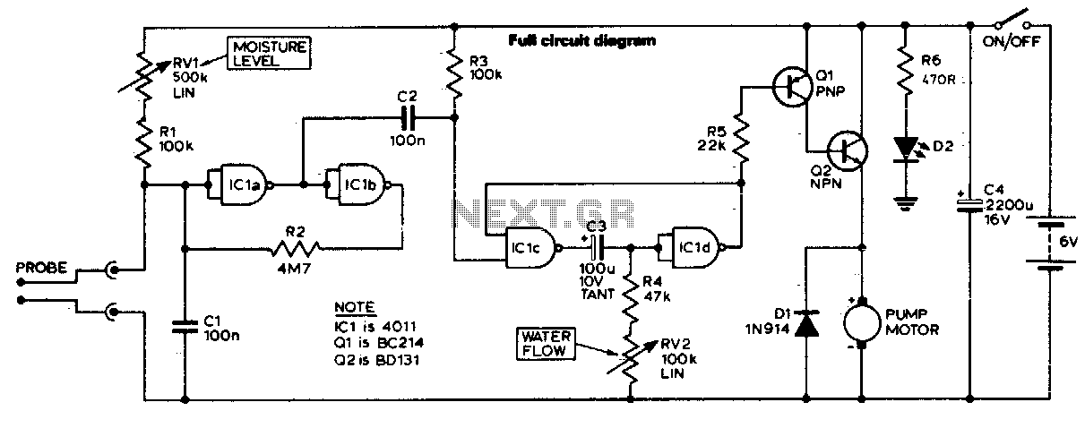
Automatic plant waterer
The unit consists of a sensor, timer, and electric water pump. The sensor is embedded in the soil, and when dry, the electronics operate the water pump for a preset time. The circuit is composed of a level-sensitive Schmitt trigger,...
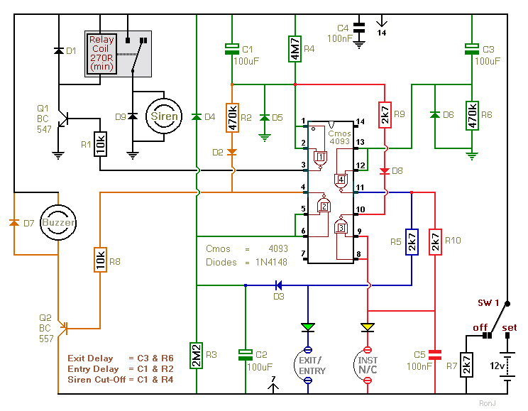
Two-Zone Burglar Alarm circuit
This two-zone alarm features automatic exit, entry, and siren cut-off timers. It was designed for the Beginner's Guide to CMOS Timers, providing a particularly detailed circuit description. An optional One-Time-Only module is available, which will deactivate the siren after the...
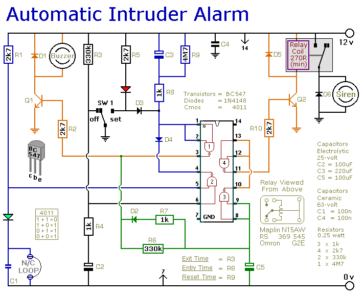
A Simpler Cmos Single Zone Alarm circuit
This is a simple single-zone burglar alarm circuit. Its features include automatic exit and entry delays and a timed bell/siren cut-off. It is designed to be used with the usual types of normally-closed input devices such as magnetic reed contacts,...
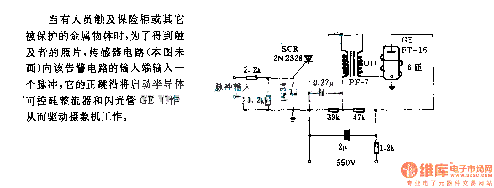
The alarm circuit diagram for safety box and other metal objects
When an individual touches the safety box or other protected metal objects, the sensor circuit generates a pulse to the alarm circuit. The positive edge of this pulse activates the semiconductor and thyristor flash GE, subsequently triggering the camera to...
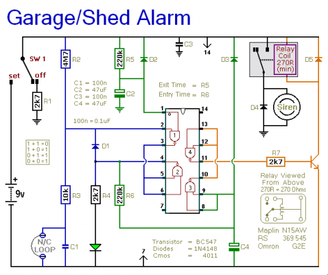
shed garage alarm
This is a basic single-zone burglar alarm circuit. Its features include automatic exit and entry delays, as well as an optional siren cut-off timer. It has an extremely low standby current, making it ideal for battery-powered operation. This circuit can...

Key Code Combination High Security Door Lock
This project involves an electronic lock that supports numerous combinations, which can be easily modified. It unlocks only with the correct sequence of four consecutive numbers. A significant feature of this electronic lock is that the four numbers must be...