


Latest Intruder Alarm Super Sensitive circuit and explantion
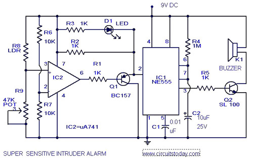
Description: The circuit diagram illustrates an ultra-sensitive intruder alarm. The mere shadow of an intruder passing within a few meters of the circuit is sufficient to activate the alarm. In this setup, the IC2 uA741 is configured as a sensitive comparator, with the set point determined by resistors R6 and R7. The voltage division created by the LDR (Light Dependent Resistor) and R9 is applied to the non-inverting pin of IC2. In standby mode, these two voltages are balanced by adjusting R9. Consequently, the output at pin 6 of the comparator remains high, keeping transistor Q1 off. The voltage at the trigger pin of IC1 is positive, resulting in no alarm activation. When an intruder approaches the LDR, the shadow cast increases its resistance.
The ultra-sensitive intruder alarm circuit employs a uA741 operational amplifier configured as a comparator to detect changes in light intensity caused by an intruder's shadow. The LDR, which is sensitive to light, is paired with a fixed resistor (R9) to create a voltage divider that feeds into the non-inverting input of the uA741. Resistors R6 and R7 set the reference voltage level against which the LDR voltage is compared.
In normal operation, the circuit is calibrated such that the voltage across the LDR and R9 is equal to the voltage set by R6 and R7. This balance keeps the output of the uA741 high, which turns off transistor Q1, preventing the alarm from sounding. The alarm remains inactive until a change in light intensity occurs, which is detected when an intruder's shadow increases the resistance of the LDR.
As the shadow falls on the LDR, the voltage at the non-inverting input drops below the reference voltage, causing the output of the comparator to switch low. This transition turns on transistor Q1, which can be configured to activate an alarm system, such as a siren or a notification system. The design allows for sensitivity adjustments through R9, enabling the user to fine-tune the response threshold based on environmental lighting conditions and desired sensitivity to intrusions.
Overall, this circuit design effectively combines simple components to create a reliable intruder detection system that can be utilized in various security applications.Here is the circuit diagram of an ultra sensitive intruder alarm. The shadow of an intruder passing few meters nearby the circuit is enough to trigger the alarm. Here IC2 uA 741 is wired as a sensitive comparator, whose set point is set by R6 &R7. The voltage divide by LDR and R9 is given at non inverting pin of IC2. At standby mode these two voltage s are set equal by adjusting R9. Now the out put (pin6) of comparator will be high. Transistor Q1 will be off. The voltage at trigger pin of IC1 will be positive and there will be no alarm. When there is an intruder near the LDR the shadow causes its resistance to increase. [. ] Disclaimer All files are found using legitimate search engine techniques. This site does not and will not condone hacking into sites to create the links it list. We will and do assume that all links found on the search engines we use are obtained in a legal manner and the webmasters are aware of the links listed on the search engines. If you find a URL that belongs to you, and you did not realize that it was "open to the public", please use the report button to notify the blogmaster of your request to remove it or it will remove within 24 hours.
This is not an invitation for webblog haters to spam with requests to remove content they feel that is objectionable and or unacceptable. Proof of URL ownership is required. NOTICE: This Blog Has Already Been Reviewed And Accepted By Blogger. com
The ultra-sensitive intruder alarm circuit employs a uA741 operational amplifier configured as a comparator to detect changes in light intensity caused by an intruder's shadow. The LDR, which is sensitive to light, is paired with a fixed resistor (R9) to create a voltage divider that feeds into the non-inverting input of the uA741. Resistors R6 and R7 set the reference voltage level against which the LDR voltage is compared.
In normal operation, the circuit is calibrated such that the voltage across the LDR and R9 is equal to the voltage set by R6 and R7. This balance keeps the output of the uA741 high, which turns off transistor Q1, preventing the alarm from sounding. The alarm remains inactive until a change in light intensity occurs, which is detected when an intruder's shadow increases the resistance of the LDR.
As the shadow falls on the LDR, the voltage at the non-inverting input drops below the reference voltage, causing the output of the comparator to switch low. This transition turns on transistor Q1, which can be configured to activate an alarm system, such as a siren or a notification system. The design allows for sensitivity adjustments through R9, enabling the user to fine-tune the response threshold based on environmental lighting conditions and desired sensitivity to intrusions.
Overall, this circuit design effectively combines simple components to create a reliable intruder detection system that can be utilized in various security applications.Here is the circuit diagram of an ultra sensitive intruder alarm. The shadow of an intruder passing few meters nearby the circuit is enough to trigger the alarm. Here IC2 uA 741 is wired as a sensitive comparator, whose set point is set by R6 &R7. The voltage divide by LDR and R9 is given at non inverting pin of IC2. At standby mode these two voltage s are set equal by adjusting R9. Now the out put (pin6) of comparator will be high. Transistor Q1 will be off. The voltage at trigger pin of IC1 will be positive and there will be no alarm. When there is an intruder near the LDR the shadow causes its resistance to increase. [. ] Disclaimer All files are found using legitimate search engine techniques. This site does not and will not condone hacking into sites to create the links it list. We will and do assume that all links found on the search engines we use are obtained in a legal manner and the webmasters are aware of the links listed on the search engines. If you find a URL that belongs to you, and you did not realize that it was "open to the public", please use the report button to notify the blogmaster of your request to remove it or it will remove within 24 hours.
This is not an invitation for webblog haters to spam with requests to remove content they feel that is objectionable and or unacceptable. Proof of URL ownership is required. NOTICE: This Blog Has Already Been Reviewed And Accepted By Blogger. com
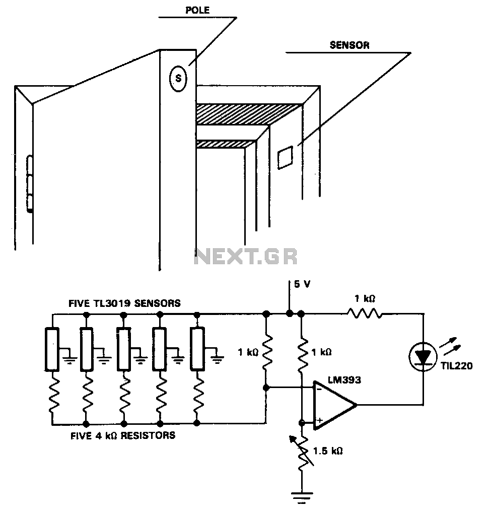
Security-door-ajar-alarm
The TL3019 device activates, or goes low, when a south pole of a magnet approaches the chip face. In this example, there are five doors, each equipped with a magnet embedded in its edge, with the south pole facing outward....
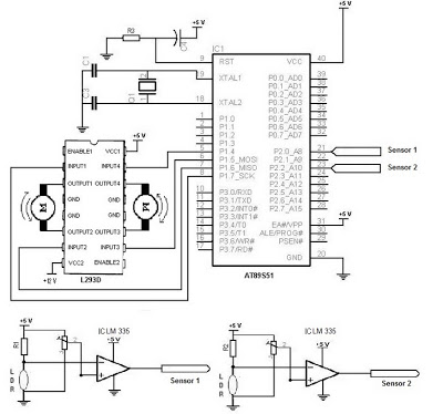
Electronic Schematic Diagram of Light Detector Robot using Light Dependent Resistor (LDR)
The electronic schematic of the Light Detector Robot can be divided into three main components: the sensor, the microcontroller, and the DC motor driver. The light sensor utilized in this design is a Light Dependent Resistor (LDR), which alters its...
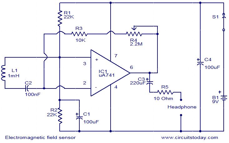
Electromagnetic Field SensorCircuit Based On The uA741 IC
The following circuit illustrates an Electromagnetic Field Sensor Circuit Diagram. This circuit is based on the uA741 integrated circuit. Features: it is used to sense electromagnetic fields.
The Electromagnetic Field Sensor Circuit utilizes the uA741 operational amplifier to detect variations in...
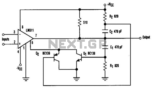
Suppress Jitter With Hysteresis Circuit
When the comparator's output transitions from low to high, the rising edge of the output pulse, differentiated by the Cl/Rl chain, activates Ql. This action blocks the comparator via its strobing input and maintains its output state for a duration...
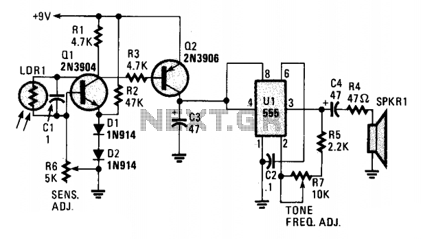
Sun wake-up call
A cadmium sulfide photocell (LDR1), which functions as a light-dependent resistor, is connected to the base and collector of an NPN transistor (Q1). When light strikes LDR1, its internal resistance decreases from a very high value (in darkness) to a...
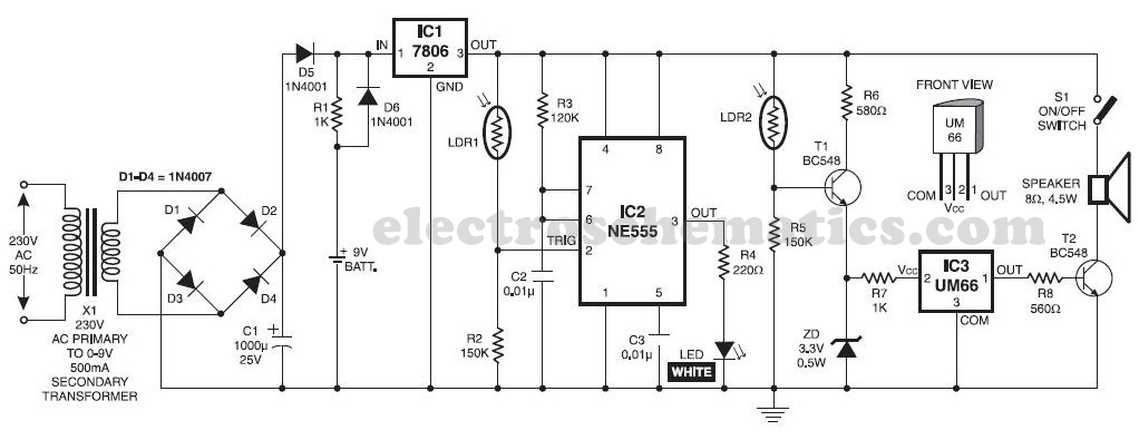
Light Alarm Circuit with LDR
This musical light alarm circuit is very simple and uses only seven components, including a light-dependent resistor (LDR) and a 3.6V battery or three 1.2V rechargeable batteries. The well-known UM66 is utilized as the sound generator, providing a pleasant wake-up...
%2Busing%2Bop%2Bamp%2B741%2Bic%2B.png "Zero Crossing Detector ZCD Comparator circuit using 741 op amp circuit")
Zero Crossing Detector (ZCD): Comparator circuit using 741 op amp
A zero crossing detector (ZCD) is a voltage comparator that switches its output between +Vsat and -Vsat (where Vsat is the saturation voltage, approximately 14V) when the input crosses the zero reference voltage. Comparators are fundamental operational amplifier circuits that...
Electronic Schematic Diagram of Light Detector Robot using Light Dependent Resistor (LDR)
The electronic schematic of the Light Detector Robot can be divided into three main components: the sensor, the microcontroller, and the DC motor driver. The light sensor utilized in this design is a Light Dependent Resistor (LDR), which alters its...

Induction high pressure alarm circuit
It utilizes the KD153 type "ding-dong" music integrated circuit (IC) to produce a "ding-dong" sound alarm. The reference number is 221611, and it is related to a refrigerator door alarm circuit.
The KD153 integrated circuit is designed specifically for generating melodic...