


Light-Beam Alarm For Intrusion Detection Circuit
#light-beam
#intrusion detection
#CDS photocell
#transistor
#SCR
#alarm bell
#electromechanical
#security
#sensor
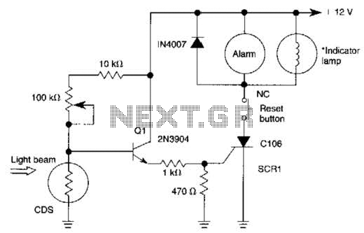
Description: When the light beam that falls on the CDS photocell is interrupted, the transistor (EN3904) conducts, triggering SCR1 (CI06) and activating the alarm bell. SI resets the SCR. The alarm bell should be a self-interrupting electromechanical type. The lamp should draw at least 100 mA to ensure SCR1 remains on during the alarm cycle.
The circuit operates as a light interruption alarm system utilizing a CDS (Cadmium Sulfide) photocell to detect changes in ambient light conditions. When an object interrupts the light beam directed at the CDS photocell, the resistance of the photocell decreases, leading to an increase in the voltage across it. This change in voltage is sufficient to turn on the EN3904 transistor, which serves as a switch in this configuration.
Once the EN3904 transistor is activated, it allows current to flow to the gate of the SCR1 (CI06), turning it on. The SCR is a semiconductor device that can latch on, meaning that once it is triggered by the EN3904, it will continue to conduct even after the triggering voltage is removed, as long as the current through it remains above a certain threshold. This characteristic is crucial for maintaining the alarm state.
The alarm bell, which is of the self-interrupting electromechanical type, is connected in such a way that it will sound when SCR1 is conducting. The design specifies that the lamp associated with the alarm should draw a minimum of 100 mA. This ensures that the current flowing through SCR1 remains above the holding current required to keep it in the on state during the alarm cycle.
To reset the SCR and silence the alarm, a switch (SI) is incorporated into the circuit. When SI is activated, it interrupts the current flowing through the SCR, allowing it to turn off and thereby resetting the system. The overall design emphasizes reliability and responsiveness to light interruptions, making it suitable for applications such as security systems or automated alerts. When the light beam that falls in the CDS photocell is interrupted, transistor (EN3904) conducts thereby triggering SCR1 (CI06) and activating alarm bell. SI resets the SCR. The alarm bell should be a self-interrupting electromechanical type. Lamp should draw at least 100 mA to sensure SCR1 remaining on during alarm cycle
The circuit operates as a light interruption alarm system utilizing a CDS (Cadmium Sulfide) photocell to detect changes in ambient light conditions. When an object interrupts the light beam directed at the CDS photocell, the resistance of the photocell decreases, leading to an increase in the voltage across it. This change in voltage is sufficient to turn on the EN3904 transistor, which serves as a switch in this configuration.
Once the EN3904 transistor is activated, it allows current to flow to the gate of the SCR1 (CI06), turning it on. The SCR is a semiconductor device that can latch on, meaning that once it is triggered by the EN3904, it will continue to conduct even after the triggering voltage is removed, as long as the current through it remains above a certain threshold. This characteristic is crucial for maintaining the alarm state.
The alarm bell, which is of the self-interrupting electromechanical type, is connected in such a way that it will sound when SCR1 is conducting. The design specifies that the lamp associated with the alarm should draw a minimum of 100 mA. This ensures that the current flowing through SCR1 remains above the holding current required to keep it in the on state during the alarm cycle.
To reset the SCR and silence the alarm, a switch (SI) is incorporated into the circuit. When SI is activated, it interrupts the current flowing through the SCR, allowing it to turn off and thereby resetting the system. The overall design emphasizes reliability and responsiveness to light interruptions, making it suitable for applications such as security systems or automated alerts. When the light beam that falls in the CDS photocell is interrupted, transistor (EN3904) conducts thereby triggering SCR1 (CI06) and activating alarm bell. SI resets the SCR. The alarm bell should be a self-interrupting electromechanical type. Lamp should draw at least 100 mA to sensure SCR1 remaining on during alarm cycle
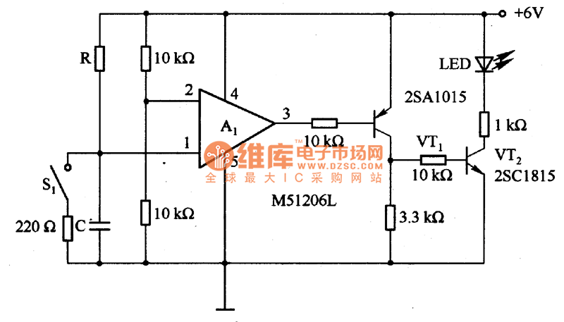
The time delay circuit diagram composed of transistor
The circuit is designed to set a delay time based on the voltage Us and the resistor R. In this configuration, S1 acts as the discharge switch for capacitor C. When switch S1 is closed, the stored charge in capacitor...
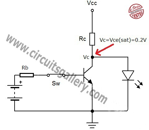
Transistor act as a switch
A transistor is a semiconductor device utilized for switching and amplifying weak signals. This article details the operation of a transistor and its function as a switch. Currently, transistors are integrated into most electronic equipment for switching applications, with digital...
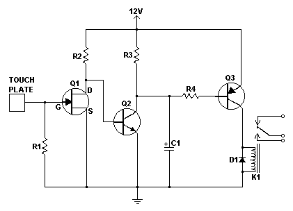
simple touch switch circuit
Similar to the CMOS-based touch switch available on this site, this transistor-based touch switch can activate a load simply by the user touching a metal plate. It is designed to directly switch a relay, allowing it to be used with...
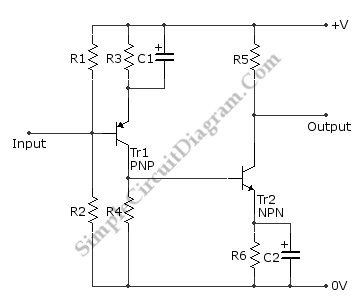
DC Coupled Transistor Amplifier
This is a directly coupled (DC) amplifier circuit. It is constructed using NPN and PNP transistors and is designed to amplify direct current (DC) signals.
The directly coupled amplifier circuit utilizes both NPN and PNP transistors to achieve its amplification. In...
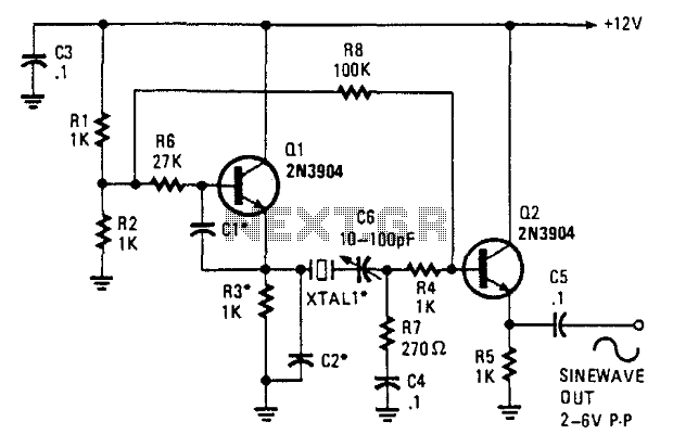
Two-Transistor Sine-Wave Oscillator
This oscillator employs two transistors and operates the crystal in its fundamental mode. Capacitors CT and C2 should be approximately 2,700 pF for 1 MHz, 680 pF for 5 MHz, and 330 pF for 10 MHz. A capacitance of 150...
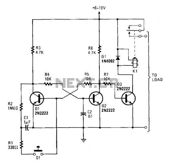
Push-on-push-off electronic switch
Transistors Q1 and Q2 form a flip-flop configuration, while Q3 operates a reed relay. Upon initial power application to the circuit, Q1 and Q3 are in a conducting state, whereas Q2 remains off. A momentary closure of switch S1 triggers...
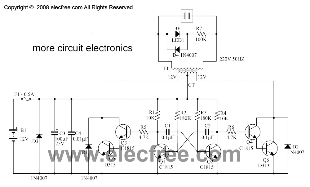
mini inverter 10w 30w by transistor d313
This is a small inverter rated at 30 watts. It converts DC voltage from a 12V battery to AC voltage of 220V-230V at a frequency of 50Hz, which is the same electricity used in households. It can power 2-3 air...
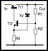
Regulation with transistors
This page discusses the various ways that a voltage regulator can be made using two transistors. If one of these transistors is the series-pass element, then the other must be the error amplifier, so there is a distinct limit to...
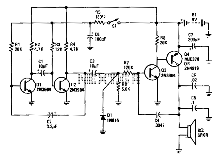
Electronic-bird-chirper
Transistors Q1 and Q2 form the two halves of a free-running multivibrator, with the frequency determined by the voltage across capacitor C8. This capacitor is charged and discharged by the operation of switch S1. Transistors Q3 and Q4 constitute a...