


Light Fence Security Alarm Circuit Schematic
#light fence
#security alarm
#photo transistor
#4093 IC
#12V power supply
#door alarm
#gate alarm
#pathway alarm
#low-frequency astable
#green LED
Description: A simple light fence security beeper is presented. This circuit can function as a door alarm, gate alarm, pathway alarm, etc. It can be powered by any 12 Volt DC power supply. The operation of this circuit is straightforward. In standby mode, phototransistor T1 receives light from the green LED (D1), causing T1 to conduct and disable the gated low-frequency astable circuit built around IC1 (4093). When the light path is interrupted by any object, T1 ceases conduction, and IC1 is activated by the low level at its input points (pins 12 and 13). Consequently, the piezo buzzer begins to beep at a slow rate determined by the circuit values of R3, R4, and C1. The red LED (D2) serves as a visual warning indicator. With a suitable reflector and lens assembly, the length of the light path can be increased, with a minimum range of 1 to 2 meters achievable using a high-brightness green LED as D1. A laser pointer can also be utilized as the light source.
The light fence security beeper circuit employs a phototransistor (T1) that acts as a light sensor, which is critical for detecting interruptions in the light path. The circuit is designed around the 4093 integrated circuit (IC1) configured as a low-frequency astable multivibrator. In its idle state, the circuit remains inactive as long as T1 is conducting, which occurs when it receives light from the green LED (D1). The phototransistor's conduction effectively disables the astable multivibrator, preventing the piezo buzzer from sounding.
When an object obstructs the light beam from D1, T1 stops conducting, which triggers IC1 to produce a low output signal. This transition activates the piezo buzzer, generating an audible alert. The frequency and duration of the beeping sound are influenced by the resistor-capacitor (RC) timing network formed by R3, R4, and C1, allowing for customization of the alarm's characteristics.
The circuit also includes a red LED (D2) that functions as a visual indicator, alerting users to the alarm's status. The design allows for the extension of the effective light path through the use of a reflector and lens assembly, enabling detection over distances of 1 to 2 meters with a high-brightness green LED. Alternatively, a laser pointer can be integrated into the setup, providing a more focused light source for enhanced detection capabilities.
Overall, this light fence security beeper circuit is a versatile and effective solution for various security applications, offering both auditory and visual alerts in response to unauthorized access or movement within a predefined area.A simple light fence security beeper is presented here. This circuit can be used as a door alarm, gate alarm, pathway alarm, etc. Any 12 Volt dc power supply can power the whole circuit. Working of this circuit is straight forward. In standby mode photo transistor T1 receives light from the green LED (D1) and T1 conducts to disable the gated low-frequency astable built around IC1(4093). When this light path is interrupted by any object in the path, T1 stops conducting and IC1 is switched by the low level at its input point (pins 12&13). As a result the piezo-buzzer starts beeping at a slow rate determined by the in circuit values of R3, R4 & C1.
Red LED (D2) is a visual warning indicator. With the help of suitable reflector and lens assembly, length of the light path can be increased. A minimum of 1 to 2 metres is possible with a high-bright green LED as D1. A laser pointer can also be used as the light source.
The light fence security beeper circuit employs a phototransistor (T1) that acts as a light sensor, which is critical for detecting interruptions in the light path. The circuit is designed around the 4093 integrated circuit (IC1) configured as a low-frequency astable multivibrator. In its idle state, the circuit remains inactive as long as T1 is conducting, which occurs when it receives light from the green LED (D1). The phototransistor's conduction effectively disables the astable multivibrator, preventing the piezo buzzer from sounding.
When an object obstructs the light beam from D1, T1 stops conducting, which triggers IC1 to produce a low output signal. This transition activates the piezo buzzer, generating an audible alert. The frequency and duration of the beeping sound are influenced by the resistor-capacitor (RC) timing network formed by R3, R4, and C1, allowing for customization of the alarm's characteristics.
The circuit also includes a red LED (D2) that functions as a visual indicator, alerting users to the alarm's status. The design allows for the extension of the effective light path through the use of a reflector and lens assembly, enabling detection over distances of 1 to 2 meters with a high-brightness green LED. Alternatively, a laser pointer can be integrated into the setup, providing a more focused light source for enhanced detection capabilities.
Overall, this light fence security beeper circuit is a versatile and effective solution for various security applications, offering both auditory and visual alerts in response to unauthorized access or movement within a predefined area.A simple light fence security beeper is presented here. This circuit can be used as a door alarm, gate alarm, pathway alarm, etc. Any 12 Volt dc power supply can power the whole circuit. Working of this circuit is straight forward. In standby mode photo transistor T1 receives light from the green LED (D1) and T1 conducts to disable the gated low-frequency astable built around IC1(4093). When this light path is interrupted by any object in the path, T1 stops conducting and IC1 is switched by the low level at its input point (pins 12&13). As a result the piezo-buzzer starts beeping at a slow rate determined by the in circuit values of R3, R4 & C1.
Red LED (D2) is a visual warning indicator. With the help of suitable reflector and lens assembly, length of the light path can be increased. A minimum of 1 to 2 metres is possible with a high-bright green LED as D1. A laser pointer can also be used as the light source.
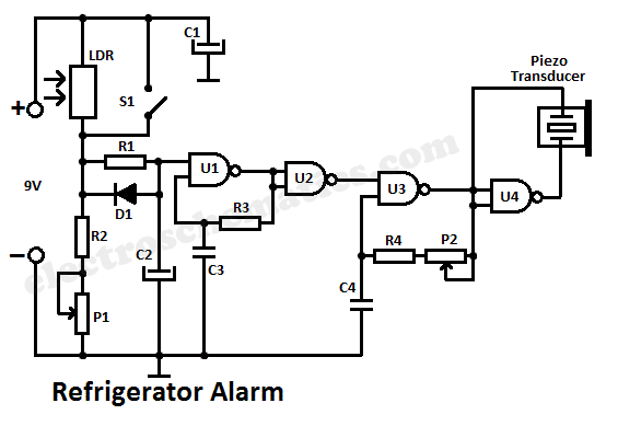
Door open alarm
Door open alarms are primarily utilized in automotive, industrial, and appliance applications. This type of circuit can detect when a refrigerator door is opened. Upon opening the door, a triac may be activated to manage the internal light. The circuit...
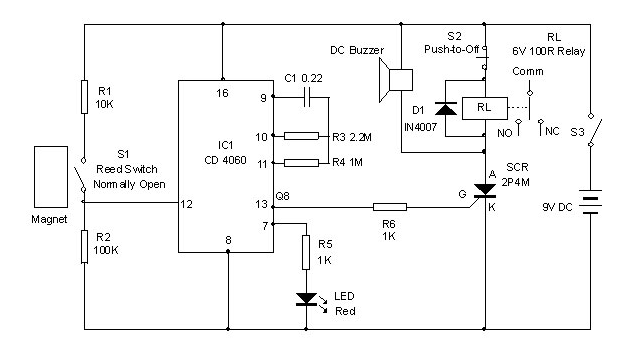
Simple Door Alarm Project
Simple Burglar Alarm / Door Alarm Circuit Diagram. This project can be utilized to secure a door or window. It emits a loud beep and activates the room light when an intruder attempts to break the door lock.
The Simple Burglar...
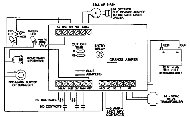
12V/1.5A Residential AlarmCircuit
The following alarm circuit is designed with features that may be suitable for residential and commercial alarm system applications. It has a 12V and 1.5A regulated power supply. Furthermore, this residential alarm circuit also includes a delay circuit, a 24-hour...
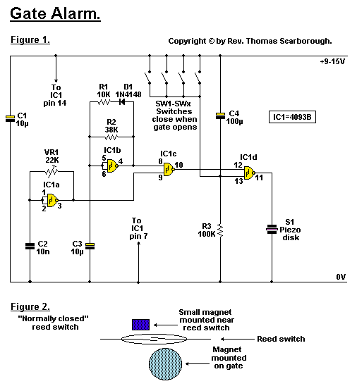
Gate Alarm Circuit
The objective is to enhance information transmission through the distribution of articles. Please contact us via email at [email protected] within 15 days if there are any issues related to article content, copyright, or other concerns. Prompt deletion will occur if...
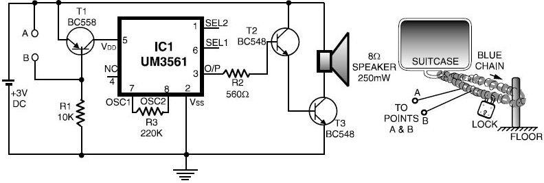
Luggage Bike Security Alarm Circuit
This luggage or bike alarm can be utilized while traveling by train or bus. Typically, luggage is secured using a chain-and-lock arrangement; however, there are still vulnerabilities.
The luggage or bike alarm system is designed to enhance the security of personal...

door alarm system schematic
This circuit schematic produces a beep and/or illuminates an LED when someone touches the door handle from outside. The alarm will continue to sound until the circuit is switched off.
The circuit operates on the principle of capacitive sensing, where the...
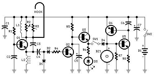
Door Alarm
This circuit emits a beep and/or illuminates a LED when someone touches the door-handle from the outside. The alarm will sound until the circuit will be switched-off. The entire circuit is enclosed in a small plastic or wooden box and...
Door Alarm
This circuit emits a beep and/or illuminates a LED when someone touches the door-handle from the outside. The alarm will sound until the circuit will be switched-off. The entire circuit is enclosed in a small plastic or wooden box and...
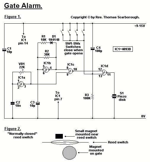
Gate Alarm
Figure 1 represents a cheap and simple Gate Alarm, that is intended to run off a small universal AC-DC power supply. IC1a is a fast oscillator, and IC1b a slow oscillator, which are combined through IC1c to emit a high...