


Ne7555 Timer For Light Sensitive Alarm Sensor
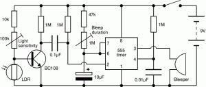
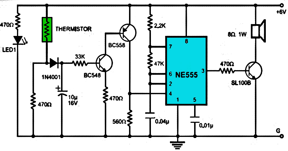
Description: This circuit illustrates the NE555 timer used in a light-sensitive alarm sensor circuit diagram. Features include the ability to detect a sudden shadow falling on the sensor.
The NE555 timer is a versatile integrated circuit widely utilized in various timing, delay, pulse generation, and oscillator applications. In this specific configuration, the NE555 timer operates as a monostable multivibrator, which triggers an alarm when a light interruption is detected.
The circuit typically consists of a light-dependent resistor (LDR) that serves as the primary sensor. The LDR changes its resistance based on the intensity of the ambient light. When a sudden shadow or a decrease in light intensity occurs, the resistance of the LDR increases, causing a voltage drop across it. This change is detected by the NE555 timer, which is configured to respond to the threshold voltage at its trigger pin.
The circuit may include a resistor-capacitor (RC) network connected to the NE555 timer, which determines the timing duration of the alarm. The output from the timer can be connected to a relay or a transistor to activate an alarm or any other output device, such as a buzzer or LED indicator.
Power supply considerations for the circuit are essential, as the NE555 timer typically operates within a voltage range of 4.5V to 15V. Proper decoupling capacitors should be placed near the power supply pins of the IC to ensure stable operation.
Overall, this light-sensitive alarm sensor circuit utilizing the NE555 timer is an effective solution for applications requiring automatic detection of light changes, providing an audible or visual alert in response to sudden shadows or light interruptions.This circuit shows about Ne7555 Timer For Light Sensitive Alarm Sensor Circuit Diagram. Features: detects a sudden shadow falling on the ..
The NE555 timer is a versatile integrated circuit widely utilized in various timing, delay, pulse generation, and oscillator applications. In this specific configuration, the NE555 timer operates as a monostable multivibrator, which triggers an alarm when a light interruption is detected.
The circuit typically consists of a light-dependent resistor (LDR) that serves as the primary sensor. The LDR changes its resistance based on the intensity of the ambient light. When a sudden shadow or a decrease in light intensity occurs, the resistance of the LDR increases, causing a voltage drop across it. This change is detected by the NE555 timer, which is configured to respond to the threshold voltage at its trigger pin.
The circuit may include a resistor-capacitor (RC) network connected to the NE555 timer, which determines the timing duration of the alarm. The output from the timer can be connected to a relay or a transistor to activate an alarm or any other output device, such as a buzzer or LED indicator.
Power supply considerations for the circuit are essential, as the NE555 timer typically operates within a voltage range of 4.5V to 15V. Proper decoupling capacitors should be placed near the power supply pins of the IC to ensure stable operation.
Overall, this light-sensitive alarm sensor circuit utilizing the NE555 timer is an effective solution for applications requiring automatic detection of light changes, providing an audible or visual alert in response to sudden shadows or light interruptions.This circuit shows about Ne7555 Timer For Light Sensitive Alarm Sensor Circuit Diagram. Features: detects a sudden shadow falling on the ..
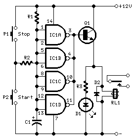
long delay timer circuit diagram
This timer was designed primarily to turn off a portable radio after a specific duration. This feature allows users to fall asleep on the beach or in a hammock, with the assurance that the radio will automatically shut off after...
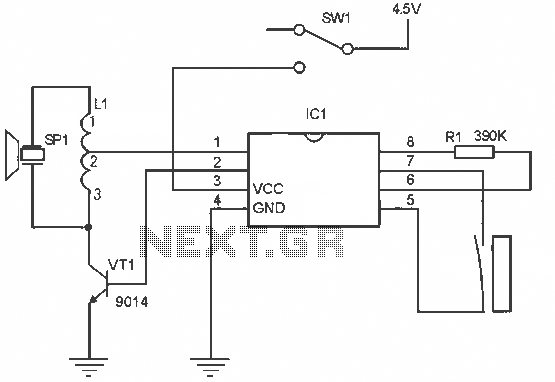
Menci alarm produced schematic circuit diagram
The alarm circuit operates as follows: When the power switch SW1 is turned on, the alarm system becomes active. If a magnet is brought close to the spring, the magnetic field attracts the spring, causing the dynamic and static switch...
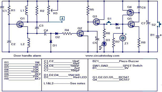
Door handle alarm
The automatic door handle alarm circuit emits an audible alarm and activates an LED when someone touches the door handle. This latching circuit continues to produce sound until it is manually turned off. Transistor Q1 is configured as an astable...
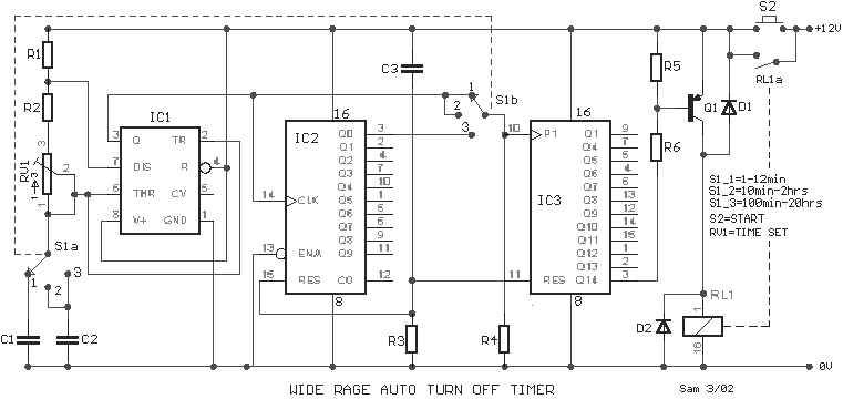
wide range timer
A wide range auto turn-off timer covering 1 minute to 20 hours in three ranges.
The auto turn-off timer is designed to provide a versatile timing solution that can be set across a broad spectrum, from a minimum of 1 minute...
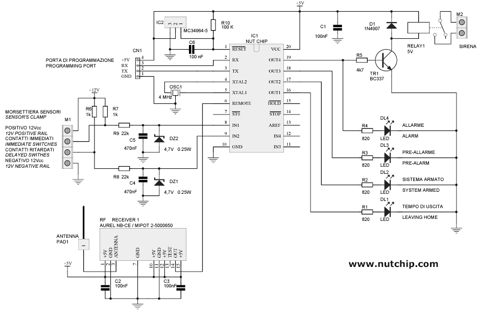
Allarm circuit
Building a personal alarm system is both practical and engaging. The most rewarding aspect is demonstrating its functionality to friends by activating the alarm remotely, saying, "I completed this in a weekend." Customizing the alarm system offers maximum flexibility, allowing...
Alarm
This is a simple and easy-to-build multi-tone alarm circuit that can be utilized in burglar alarms or sirens. The circuit is based on the dual op-amp MC1458 and LM380. The two op-amps within the MC1458 are configured to generate square...
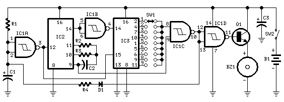
Jogging Timer
This circuit was developed since a number of visitors of this website requested a timer capable of emitting a beep after one, two, three minutes and so on, for jogging purposes. As shown in the Circuit diagram, SW1 is a...
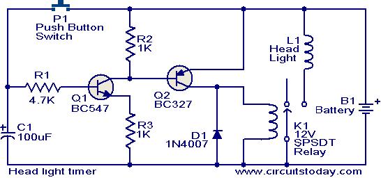
Head light timer circuit
This circuit is a compact timer that keeps the headlights of a car on for approximately 1.5 minutes before turning them off. Incorporating this circuit into a vehicle allows access to dark areas without the need to return and manually...
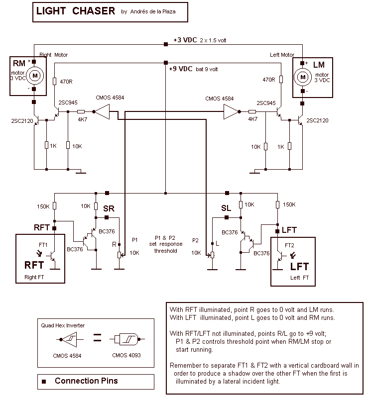
Sun Light Chaser
With RFT illuminated, point R goes to 0 volt and LM runs. With LFT illuminated, point R goes to 0 volt and RM runs. With RFT and/or LFT not illuminated, points R/L go to +9 volt; P1 and P2 controls...