


Noaa Weather Alert Decoder
#NOAA
#weather alert
#1050-Hz tone
#decoder
#RF receiver
#emergency alert
#signal detection
#weather monitoring
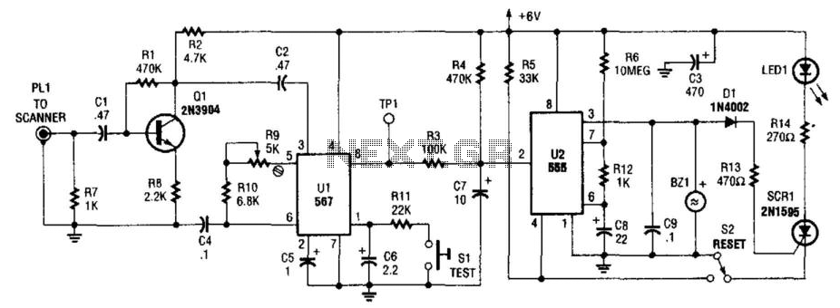
Description: This circuit detects the 1050-Hz tone transmitted by NOAA (National Oceanic and Atmospheric Administration) weather radio stations, which operate within the frequency range of 162.40 to 162.55 MHz. The tone is emitted for several seconds. Q1 functions as an amplifier that drives the tone detector U1, an NE567 integrated circuit, which identifies the tone and outputs a low signal on pin 8. This output is connected to a 555 timer (U3), which generates a high signal on pin 3, activating the buzzer BZ1, triggering SCR1, and illuminating the LED. Switch S2 is utilized to reset the circuit. Audio input is sourced from the receiver associated with the device. Switch S1 is employed for testing the device, and it will activate the alarm within two seconds if the system is functioning correctly.
The circuit operates primarily by detecting a specific audio frequency, which is crucial for alerting users to weather-related emergencies. The NE567 tone decoder is central to this operation, as it is designed to respond to a narrow band of frequencies, specifically the 1050-Hz tone used by NOAA weather broadcasts. When the tone is detected, the NE567 outputs a low signal on pin 8, indicating successful detection.
The output from the NE567 is fed into a 555 timer configured in a monostable mode. This timer is responsible for generating a pulse when triggered, which in this case occurs when the tone is detected. The pulse duration can be adjusted by changing the resistor and capacitor values connected to the timer, allowing for flexibility in how long the alarm sounds.
The buzzer (BZ1) is activated by the high output from the 555 timer, providing an audible alert to the user. Simultaneously, SCR1 is triggered, which can be used to drive additional loads, such as a relay or external alarm system, providing further notification options. The LED serves as a visual indicator that the alarm has been activated, enhancing the circuit's usability in various environments.
Resetting the circuit is accomplished through switch S2, which allows users to clear the alarm state after a warning has been acknowledged. The audio input from the receiver is crucial for the detection process, ensuring that the circuit is only activated by the intended 1050-Hz tone.
Switch S1 serves a dual purpose; it not only tests the functionality of the circuit but also simulates the detection of the tone. When activated, it ensures that the alarm system operates correctly by producing an audible alert within two seconds, confirming that the circuit components are working as intended.
Overall, this circuit is a practical solution for monitoring NOAA weather broadcasts and providing timely alerts to users, enhancing safety and preparedness in the event of severe weather conditions. This circuit detects the 1050-Hz tone sent by the NOAA (National Oceanic and Atmospheric Administration) Weather radio stations that operate from 162.40 to 162.55 MHz. This tone lasts for several seconds. Ql is an amplifier that feeds tone detector Ul, an NE567 detects this tone and produces a low on pin 8. This is coupled to a 555 timer (U3), which produces a high on its pin 3, sounds BZ1, triggers SCR1, and lights the LED.
S2 is used to rest the circuit. Audio is taken from the receiver that is used with the device. SI is used to test the device and it will sound the alarm in two seconds if all is OK.
The circuit operates primarily by detecting a specific audio frequency, which is crucial for alerting users to weather-related emergencies. The NE567 tone decoder is central to this operation, as it is designed to respond to a narrow band of frequencies, specifically the 1050-Hz tone used by NOAA weather broadcasts. When the tone is detected, the NE567 outputs a low signal on pin 8, indicating successful detection.
The output from the NE567 is fed into a 555 timer configured in a monostable mode. This timer is responsible for generating a pulse when triggered, which in this case occurs when the tone is detected. The pulse duration can be adjusted by changing the resistor and capacitor values connected to the timer, allowing for flexibility in how long the alarm sounds.
The buzzer (BZ1) is activated by the high output from the 555 timer, providing an audible alert to the user. Simultaneously, SCR1 is triggered, which can be used to drive additional loads, such as a relay or external alarm system, providing further notification options. The LED serves as a visual indicator that the alarm has been activated, enhancing the circuit's usability in various environments.
Resetting the circuit is accomplished through switch S2, which allows users to clear the alarm state after a warning has been acknowledged. The audio input from the receiver is crucial for the detection process, ensuring that the circuit is only activated by the intended 1050-Hz tone.
Switch S1 serves a dual purpose; it not only tests the functionality of the circuit but also simulates the detection of the tone. When activated, it ensures that the alarm system operates correctly by producing an audible alert within two seconds, confirming that the circuit components are working as intended.
Overall, this circuit is a practical solution for monitoring NOAA weather broadcasts and providing timely alerts to users, enhancing safety and preparedness in the event of severe weather conditions. This circuit detects the 1050-Hz tone sent by the NOAA (National Oceanic and Atmospheric Administration) Weather radio stations that operate from 162.40 to 162.55 MHz. This tone lasts for several seconds. Ql is an amplifier that feeds tone detector Ul, an NE567 detects this tone and produces a low on pin 8. This is coupled to a 555 timer (U3), which produces a high on its pin 3, sounds BZ1, triggers SCR1, and lights the LED.
S2 is used to rest the circuit. Audio is taken from the receiver that is used with the device. SI is used to test the device and it will sound the alarm in two seconds if all is OK.
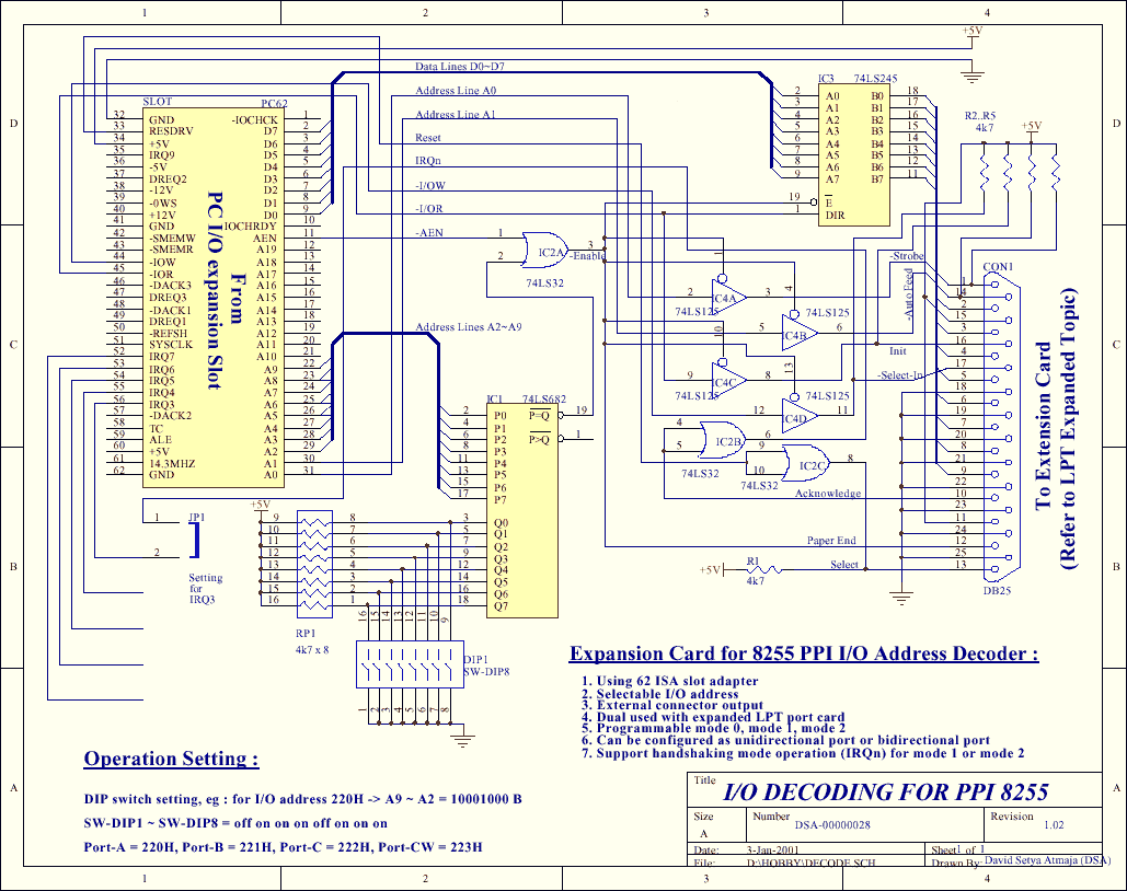
decoder circuit
The PPI-8255 is a general-purpose I/O programmable interface that is typically connected directly to a computer bus. This article demonstrates that the card can serve dual purposes: as an expander port and for direct I/O functionality. The card can be...
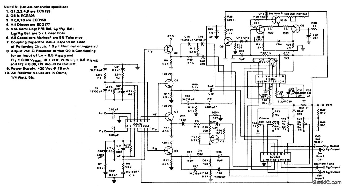
4-channel SQ logic decoder
4-channel SQ logic decoder with a current drain of 75 mA at 20 volts. The input impedance is 2M ohms, and the output impedance is 2K ohms (courtesy of GTE Sylvania Incorporated).
The 4-channel SQ logic decoder is an integrated circuit...
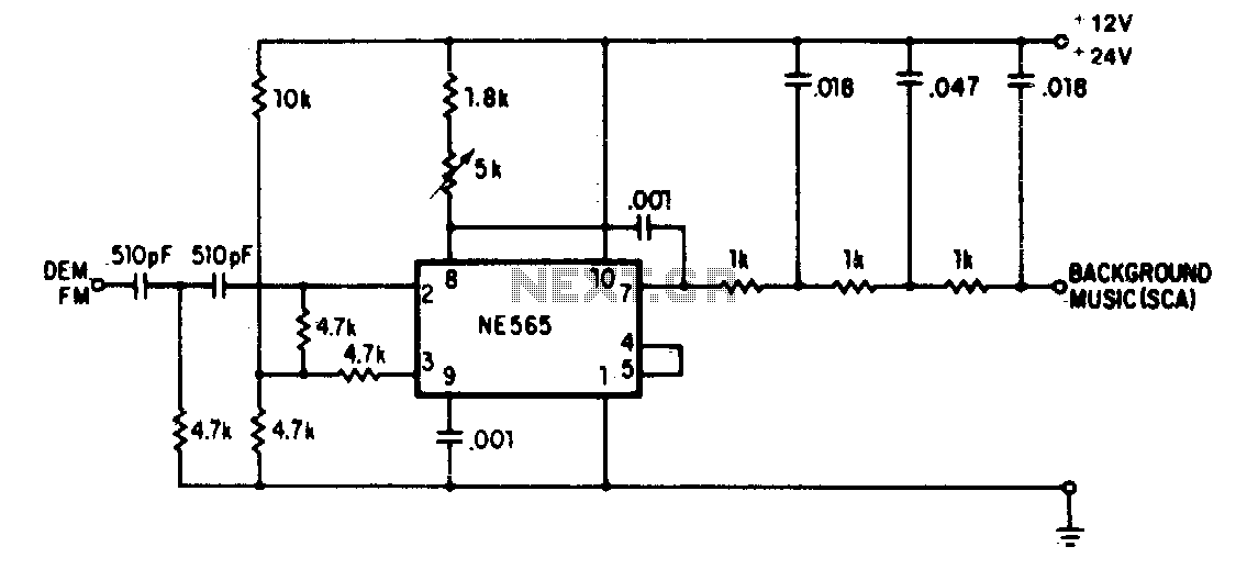
Sca background music decoder
A resistive voltage divider is utilized to establish a bias voltage for the input (pins 2 and 3). The demodulated FM signal is introduced to the input through a two-stage high-pass filter, which serves to provide capacitive coupling and to...
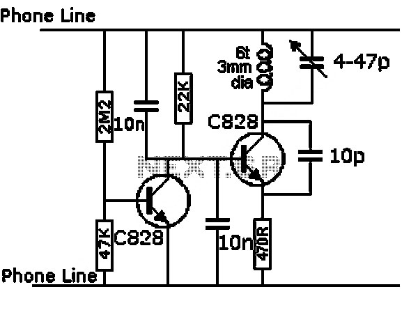
low power universal demultiplexer decoder
This circuit functions as a universal decoder, capable of operating either as a dual 1-of-4 decoder or as a single 1-of-8 decoder, depending on the signal applied to the Mode Control (M) input. In the dual mode, each section features...
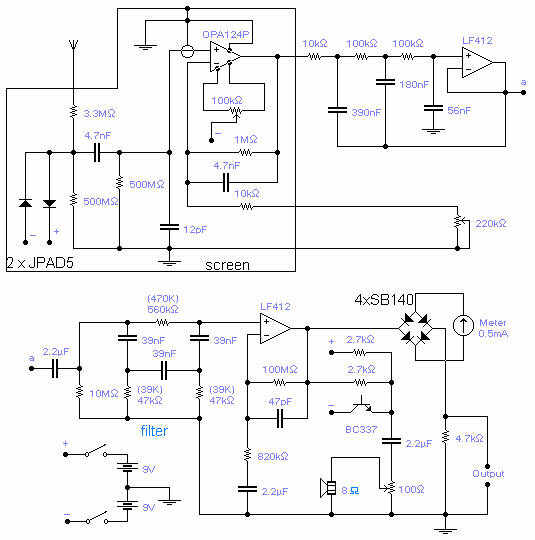
0.1Hz to 10Hz RF reciever
The frequency covered is from 0.1Hz to 10Hz and useful signals are received up to 16Hz. The first Op-Amp, properly shielded, must be installed close to the antenna (1-3m long) and connected to the rest of the circuit with a...
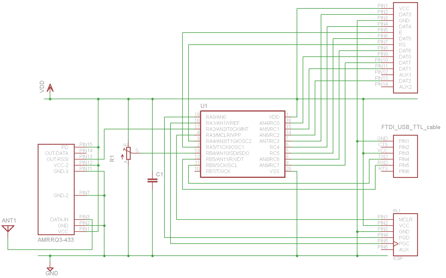
General purpose RF receiver
A sensor project that transmits its measurements via a 433 MHz wireless communication link. This document describes the details of a self-built receiver designed to receive data from this sensor. The objective is to create a general-purpose RF receiver module...
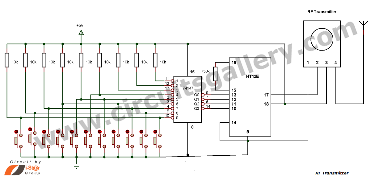
Multi Channel Remote Control System
This is a hobby circuit for a multi-channel remote control system that allows the control of eight different appliances. The primary components of this multi-channel remote control circuit are the RF receiver and transmitter. By utilizing this circuit, it is...
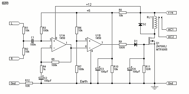
Signal Detecting Auto Power-On Unit
How many times have you wished that there was a simple way to turn on that sub-woofer or some other piece of audio equipment, simply by sending it a signal? This ability is fairly common in commercial subs and some...
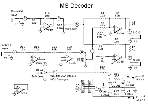
A practical MS Decoder Circuit
The schematic diagram of the MS Decoder may appear complex, but it is relatively straightforward. Initially, both the Mid and Side signals are buffered using unity gain inverting buffers, which are constructed around IC1b and IC2b. This buffering serves two...