


Piezoelectric alarm rings clear as a bell
Description: A common piezoelectric alarm, such as the Murata PKB5-3A, possesses many valuable attributes, including compactness, lightweight design, efficiency, and reliability. However, the loud, high-pitched sound output can be irritating in many applications. The circuit provided transforms this buzzer into a more pleasant-sounding bell. At the core of the circuit is the widely used 555 timer (U1), configured as an astable multivibrator. The output low time generates a short pulse that initiates the bell strike, calculated as 0.693 × R2 × C1. For the specified component values, the strike time is 6.93 ms. The output high time represents the sustain period during which the bell tone's amplitude gradually decays, calculated as 0.693 × (R1 + R2) × C1. In this configuration, the high time is 236 ms. When U1’s output is low, the series transistor switch (Q1) activates through bias resistor R3, energizing the piezoelectric alarm (AL1) and charging capacitor C3. When U1’s output is high, Q1 turns off, causing the output of AL1 to decay until C3 discharges. This cycle then repeats. The values of the timing components R1, R2, and C1, along with decay capacitor C3, are not critical, allowing for various sound effects through experimentation.
The circuit utilizes the 555 timer in an astable mode to generate a square wave output that controls the operation of the piezoelectric alarm. The timer's configuration allows for continuous oscillation, creating a rhythmic sound output. The low time (6.93 ms) corresponds to the duration of the initial bell strike, while the high time (236 ms) dictates how long the bell tone is sustained before it begins to decay.
The transistor switch (Q1) plays a crucial role in controlling the alarm. When the 555 timer outputs a low signal, Q1 is turned on, allowing current to flow through the piezoelectric alarm, producing sound. The charging of capacitor C3 during this phase helps ensure that the alarm is energized adequately. Upon transitioning to a high output from the timer, Q1 is turned off, which stops current flow to the alarm and allows the sound to decay as C3 discharges.
The timing components R1, R2, and C1 can be selected based on the desired sound characteristics. For instance, increasing R1 or R2 will extend the duration of the high time, resulting in a longer sustain phase. Alternatively, adjusting C1 will influence both the strike and sustain times. Capacitor C3's value can also be modified to create different decay rates for the sound output, allowing for customization of the alarm's auditory profile.
This circuit design is straightforward, cost-effective, and adaptable, making it suitable for various applications where a less abrasive sound output is preferred.A common piezoelectric alarm, such as the Murata (Smyrna, GA) PKB5-3A shown, has many valuable attributes. It is compact, lightweight, efficient and reliable. However, the loud, high-pitched sound output can be quite irritating in many applications. The simple and inexpensive circuit provided here transforms this obnoxious little buzzer into a ple asantsounding bell ( see the figure ). At the heart of the circuit is the popular 555 timer U1, which is configured as an astable multivibrator. The output low time is a short pulse that initiates the bell strike. The strike time is 0. 693 †” R2 †” C1. For the component values shown, the strike time is 6. 93 ms. The output high time is the sustain time during which the amplitude of the bell tone decays continuously.
The high time is 0. 693 †” (R1 + R2) †” (C1). For this circuit, the high time is 236 ms. When the output of U1 is low, the series transistor switch Q1 turns on through bias resistor R3 to energize the piezoelectric alarm AL1 and charge capacitor C3. When the output of U1 is high, Q1 is off and the output of AL1 decays until C3 is discharged. When C3 is discharged again, the cycle is repeated. The values of timing components R1, R2, and C1, along with decay capacitor C3, aren`t critical; various sound effects can be produced by experimenting with them.
The circuit utilizes the 555 timer in an astable mode to generate a square wave output that controls the operation of the piezoelectric alarm. The timer's configuration allows for continuous oscillation, creating a rhythmic sound output. The low time (6.93 ms) corresponds to the duration of the initial bell strike, while the high time (236 ms) dictates how long the bell tone is sustained before it begins to decay.
The transistor switch (Q1) plays a crucial role in controlling the alarm. When the 555 timer outputs a low signal, Q1 is turned on, allowing current to flow through the piezoelectric alarm, producing sound. The charging of capacitor C3 during this phase helps ensure that the alarm is energized adequately. Upon transitioning to a high output from the timer, Q1 is turned off, which stops current flow to the alarm and allows the sound to decay as C3 discharges.
The timing components R1, R2, and C1 can be selected based on the desired sound characteristics. For instance, increasing R1 or R2 will extend the duration of the high time, resulting in a longer sustain phase. Alternatively, adjusting C1 will influence both the strike and sustain times. Capacitor C3's value can also be modified to create different decay rates for the sound output, allowing for customization of the alarm's auditory profile.
This circuit design is straightforward, cost-effective, and adaptable, making it suitable for various applications where a less abrasive sound output is preferred.A common piezoelectric alarm, such as the Murata (Smyrna, GA) PKB5-3A shown, has many valuable attributes. It is compact, lightweight, efficient and reliable. However, the loud, high-pitched sound output can be quite irritating in many applications. The simple and inexpensive circuit provided here transforms this obnoxious little buzzer into a ple asantsounding bell ( see the figure ). At the heart of the circuit is the popular 555 timer U1, which is configured as an astable multivibrator. The output low time is a short pulse that initiates the bell strike. The strike time is 0. 693 †” R2 †” C1. For the component values shown, the strike time is 6. 93 ms. The output high time is the sustain time during which the amplitude of the bell tone decays continuously.
The high time is 0. 693 †” (R1 + R2) †” (C1). For this circuit, the high time is 236 ms. When the output of U1 is low, the series transistor switch Q1 turns on through bias resistor R3 to energize the piezoelectric alarm AL1 and charge capacitor C3. When the output of U1 is high, Q1 is off and the output of AL1 decays until C3 is discharged. When C3 is discharged again, the cycle is repeated. The values of timing components R1, R2, and C1, along with decay capacitor C3, aren`t critical; various sound effects can be produced by experimenting with them.
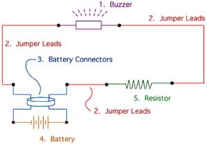
buzzer circuit diagram
The drive circuit is a basic drive recently designed to accommodate a 27mm passive piezoelectric buzzer, aiming for a sound output exceeding 100dB while minimizing power consumption. Due to constraints related to product cost and structural size, the circuit utilizes...
16 bit sound
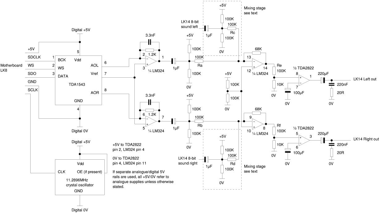
On several occasions, Acorn's initial specifications for a new machine and the final product have differed considerably in the features they provide. For example, the Risc PC's motherboard SCSI controller and Phoebe's ultra-fast scratch memory were consigned to history before...
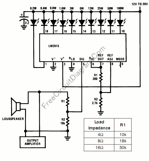
Audio Power Meter: Shows Your Audio Amplifier
This circuit allows for the measurement of the actual output power of an amplifier. It can be housed in a box to function as a measurement instrument.
The circuit for measuring amplifier output power typically includes a few essential components: a...
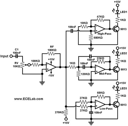
Audio Simple Sound-to-Light Converter Schematic Diagram
Figure 1 illustrates a simple circuit designed for converting an audio signal (such as one from the output terminals of a CD player). The circuit primarily consists of a buffer/amplifier stage and three filtering circuits: a high-pass filter, a band-pass...
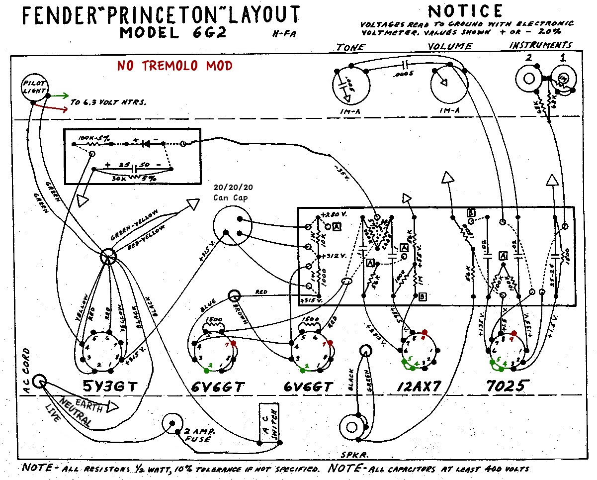
6G2 amp volume and tone play up on one input only
A newcomer is seeking a welcoming environment and expresses a desire to share a considerable amount of information.
In the context of electronic schematics, it is essential to facilitate an inclusive environment for individuals at all levels of expertise. This can...
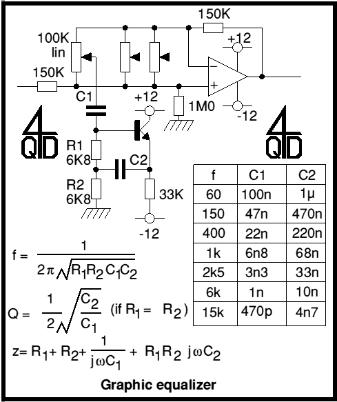
Audio Graphic Equaliser
Cleaned Input:
Description: Audio graphic equalizers are very common as commercial products (for Hi-fi, car audio and stage use) but circuits for them are very rarely published. I didn't design this one but it's really very simple. The details shown...
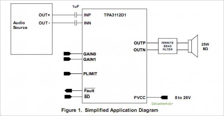
TPA3112D1 25-W FILTER-FREE MONO CLASS-D AUDIO POWER AMPLIFIER With SPEAKER GUARDß„
The TPS3803 and TPS3805 families of supervisory circuits offer circuit initialization and timing supervision, mainly for digital signal processors (DSPs) and processor-based systems. The TPS3803G15 device features a fixed-sense threshold voltage (VIT) determined by an internal voltage divider, while the...
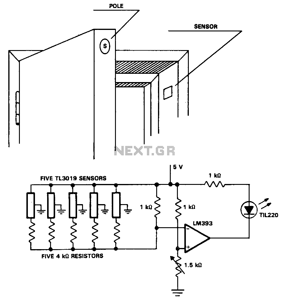
Security-door-ajar-alarm
The TL3019 device activates, or goes low, when a south pole of a magnet approaches the chip face. In this example, there are five doors, each equipped with a magnet embedded in its edge, with the south pole facing outward....
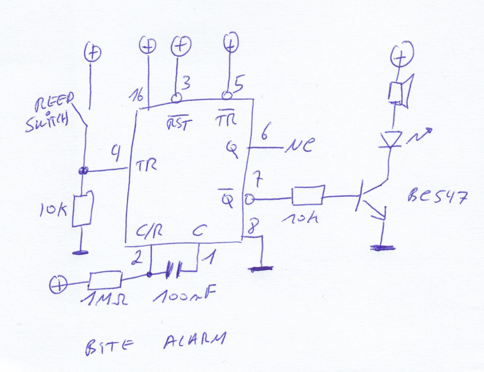
buzzer only beep once
A bite alarm, commonly used in fishing, typically emits a beeping sound when the fishing line passes over a wheel equipped with notches that facilitate optical switching, resulting in a beep-beep-beep sound until the wheel stops. However, the specific alarms...