


Precision Light-Activated Alarm Circuit
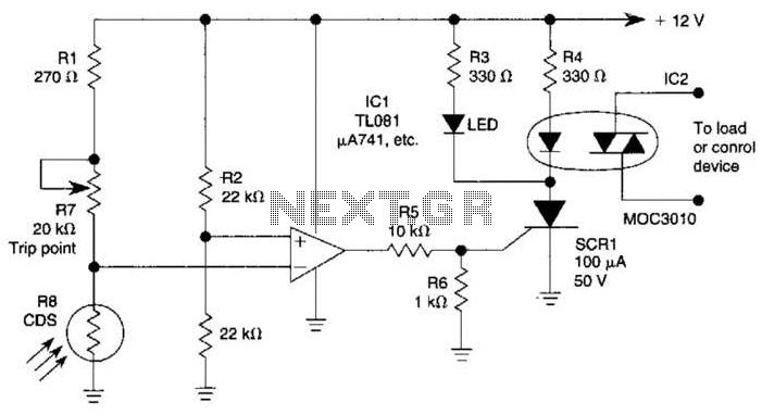
Description: The light-sensitive CDS cell R8 is configured in a bridge circuit with IC1 functioning as a comparator. When light strikes the CDS cell R8, the output of IC1 goes high, triggering SCR1. This action illuminates LED1 and activates opto isolator IC2, which subsequently switches the load.
The circuit utilizes a light-dependent resistor (CDS cell R8) that changes its resistance based on the intensity of light it receives. In this configuration, R8 is part of a bridge circuit, which typically consists of four resistors arranged in a diamond shape. The bridge circuit is balanced under normal lighting conditions, and when light intensity changes, it causes an imbalance, resulting in a voltage difference that is detected by the comparator IC1.
IC1 compares the voltage across the bridge circuit to a reference voltage. When the light intensity exceeds a certain threshold, the voltage at one of the bridge's nodes rises above the reference level, causing the output of IC1 to transition to a high state. This output signal is then used to trigger SCR1 (Silicon Controlled Rectifier), which is a type of thyristor that can control high power loads.
Upon triggering, SCR1 allows current to flow through its anode to cathode, effectively activating the connected load. In this circuit, the load activation is indicated by the illumination of LED1, which serves as a visual indicator of the system's operation. Additionally, the activation of SCR1 also energizes opto isolator IC2. The opto isolator is crucial for providing electrical isolation between the control circuit and the load circuit, ensuring that the low voltage control side does not interfere with the high voltage load side. This design enhances safety and protects sensitive components from potential damage due to high voltage spikes.
Overall, this circuit effectively demonstrates a light-sensing mechanism that can control electrical loads based on ambient light levels, utilizing a combination of analog components and semiconductor devices for efficient operation. The light-sensitive CDS cell R8 configured in a bridge circuit with IC1 as a comparator causes ICl`s output to go high when light strikes the CDS cell R8, triggering SCR1. This lights LED1 and turns on opto isolator IC2, which switches the load.
The circuit utilizes a light-dependent resistor (CDS cell R8) that changes its resistance based on the intensity of light it receives. In this configuration, R8 is part of a bridge circuit, which typically consists of four resistors arranged in a diamond shape. The bridge circuit is balanced under normal lighting conditions, and when light intensity changes, it causes an imbalance, resulting in a voltage difference that is detected by the comparator IC1.
IC1 compares the voltage across the bridge circuit to a reference voltage. When the light intensity exceeds a certain threshold, the voltage at one of the bridge's nodes rises above the reference level, causing the output of IC1 to transition to a high state. This output signal is then used to trigger SCR1 (Silicon Controlled Rectifier), which is a type of thyristor that can control high power loads.
Upon triggering, SCR1 allows current to flow through its anode to cathode, effectively activating the connected load. In this circuit, the load activation is indicated by the illumination of LED1, which serves as a visual indicator of the system's operation. Additionally, the activation of SCR1 also energizes opto isolator IC2. The opto isolator is crucial for providing electrical isolation between the control circuit and the load circuit, ensuring that the low voltage control side does not interfere with the high voltage load side. This design enhances safety and protects sensitive components from potential damage due to high voltage spikes.
Overall, this circuit effectively demonstrates a light-sensing mechanism that can control electrical loads based on ambient light levels, utilizing a combination of analog components and semiconductor devices for efficient operation. The light-sensitive CDS cell R8 configured in a bridge circuit with IC1 as a comparator causes ICl`s output to go high when light strikes the CDS cell R8, triggering SCR1. This lights LED1 and turns on opto isolator IC2, which switches the load.
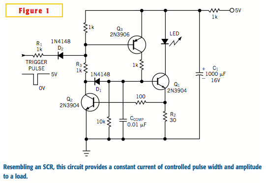
Circuit forms constant-current SCR
A typical silicon-controlled rectifier (SCR) requires a trigger current to latch on. Once the device is latched, the current flowing through the SCR is determined only by the external component values. The SCR lacks the ability to limit current flow...
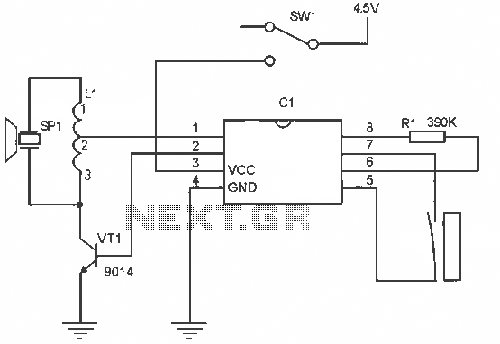
Menci alarm produced schematic circuit diagram
The alarm circuit operates as follows: When the power switch SW1 is turned on, the alarm system becomes active. If a magnet is brought close to the spring, the magnetic field attracts the spring, causing the dynamic and static switch...
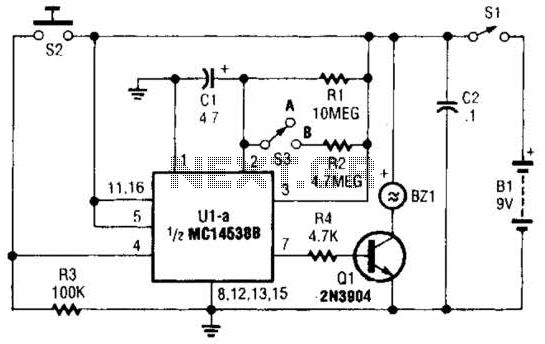
No Doze Alarm Circuit
This circuit emits a loud tone if the input switch (S2) is not retriggered at designated intervals. If the user falls asleep and fails to re-trigger the circuit, it will continue to sound until S2 is pressed.
The circuit operates on...
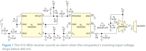
Simple Alarm Circuit Keeps Wandering Children
The receiver circuit in Figure 1 activates an audio alarm when the transmitter (Figure 2) moves beyond a specified perimeter. The transmitter functions as a voltage-controlled oscillator, operating at approximately 915 MHz within the unlicensed ISM (industrial/scientific/medical) band. It features...
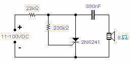
Simple SCR oscillator
Silicon controlled rectifiers (SCR) can easily oscillate if there is an inductor (a speaker coil in this case) which gives just enough extra voltage to completely switch off the sustain current. In this way a new cycle may start and...
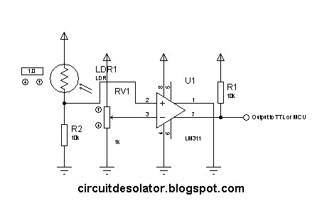
simple analog comparator
This is a common circuit block utilized in both digital and analog electronics. Its output depends on the relationship between its two input pins. One input is designated to provide the reference voltage, while the other is typically connected to...
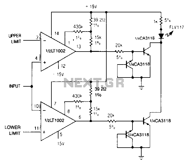
Dual-limit-microvolt-comparator
When the upper or lower limit is exceeded, the LED lights up. Positive feedback to one of the nulling terminals creates 5 to 20 pV of hysteresis on both amplifiers. This feedback changes the offset voltage of the LT1002 by...
%2Busing%2Bop%2Bamp%2B741%2Bic%2B.png "Zero Crossing Detector ZCD Comparator circuit using 741 op amp circuit")
Zero Crossing Detector (ZCD): Comparator circuit using 741 op amp
A zero crossing detector (ZCD) is a voltage comparator that switches its output between +Vsat and -Vsat (where Vsat is the saturation voltage, approximately 14V) when the input crosses the zero reference voltage. Comparators are fundamental operational amplifier circuits that...
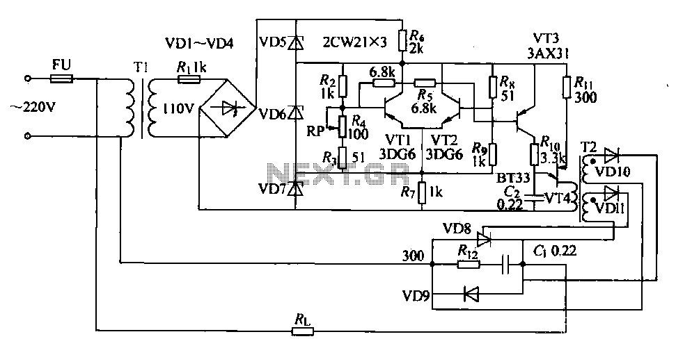
SCR furnace temperature regulating circuit
The circuit consists of two differential amplifier transistors configured with a voltage dividing type bias circuit, measuring the resistance of four arms in a bridge configuration. The product includes a platinum resistance sensor, which exhibits an increase in resistance with...